Mechanical seal for agitated reactor stirring shaft

A technology of mechanical seals and stirring shafts, applied in the direction of engine seals, mechanical equipment, engine components, etc., can solve the problems of material pollution, troublesome disassembly and assembly, economic losses, etc., to reduce the difficulty of replacement, simple disassembly and assembly, and avoid pollution Effect

Inactive Publication Date: 2012-02-22
NINGBO DONGLIAN MECHANICAL SEAL
View PDF5 Cites 4 Cited by
  • Summary
  • Abstract
  • Description
  • Claims
  • Application Information

AI Technical Summary

Problems solved by technology

The mechanical seal for the stirring shaft of the reactor with the above structure still has the following three disadvantages in the actual use process: 1. Since the mechanical seal for the stirring shaft of the reactor in the prior art is provided with a cooling liquid tank outside the moving ring and the static ring, As a result, the volume of the entire mechanical seal is larger, which inevitably requires a larger installation space; 2. During long-term use, as the sealing ring in the mechanical seal gradually ages, the sealing performance of the sealing ring will be greatly reduced. , the coolant located in the coolant tank may leak and penetrate into the reactor along with the gap between the parts in the mechanical seal, so that the materials in the reactor are easily polluted and scrapped, resulting in unnecessary 3. When the mechanical seal is damaged and needs to be replaced, the staff needs to drain the coolant in the coolant tank before removing the damaged mechanical seal, then install a new mechanical seal, and finally add the Coolant, so it is very troublesome to disassemble, which greatly increases the difficulty of replacing the mechanical seal

Method used


Image

  • Mechanical seal for agitated reactor stirring shaft
  • Mechanical seal for agitated reactor stirring shaft
  • Mechanical seal for agitated reactor stirring shaft

Examples


Embodiment Construction

[0019] The mechanical seal for the stirring shaft of the reactor of the present invention will be further described in detail below in conjunction with the accompanying drawings and specific embodiments.

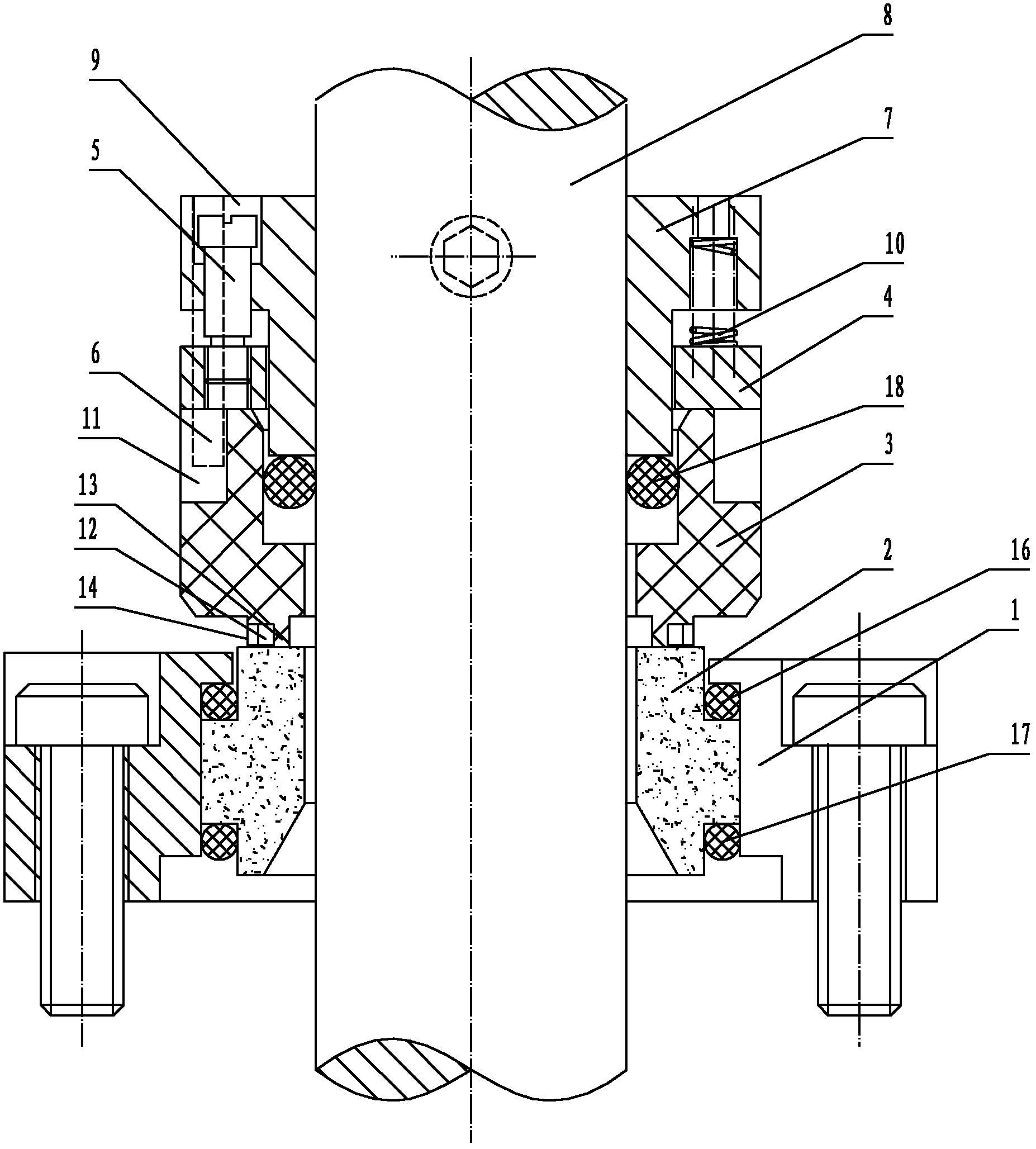
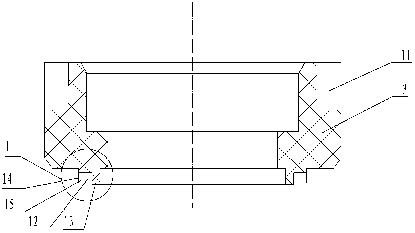
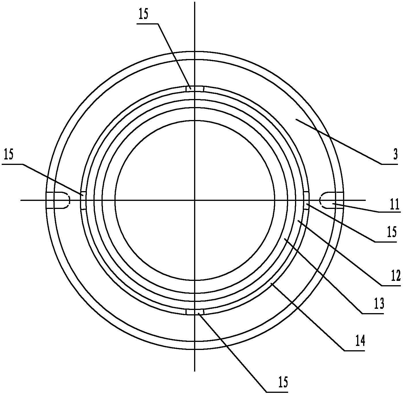
[0020] Such as figure 1 , figure 2 , image 3 and Figure 4 As shown, in this specific embodiment, the mechanical seal for the stirring shaft of the reaction kettle of the present invention includes a static ring seat 1, a static ring 2, a moving ring 3, a push ring 4, a transmission screw 5, a transmission pin 6, and a connection with the stirring shaft 8. The moving ring seat 7 and a number of springs 10 evenly distributed on the moving ring seat 7 in the circumferential direction, the push ring 4 is set on the moving ring seat 7, the transmission screw 5 is slidably inserted in the through hole 9 of the moving ring seat 7, and the transmission screw The lower end of 5 is connected with the push ring 4, the spring 10 is placed between the moving ring seat 7 and the pus...


PUM

PropertyMeasurementUnit
Groove widthaaaaaaaaaa

Abstract

The invention discloses a mechanical seal for an agitated reactor stirring shaft, which comprises a mating ring adapter, a mating ring, a moving ring, a driving ring, a driving screw, a driving pin, a moving ring adapter which is connected with a stirring shaft and a plurality of springs which are uniformly circumferentially arranged on the moving ring adapter, the driving ring is sleeved on the moving ring adapter, the driving screw is inserted in a through hole of the moving ring adapter in a sliding manner, the lower end of the driving screw is connected with the driving ring, the springs support between the moving ring adapter and the driving ring, the upper end of the moving ring is attached to the driving ring, the upper end of the driving pin is connected with the moving ring adapter and the lower end of the driving pin is arranged in a pin groove of the moving ring, the mating ring adapter is sleeved on the mating ring, the lower end surface of the moving ring is provided with a circular groove, the height of the inner wall of the circular groove relative to the groove bottom is greater than that of the outer wall relative to the groove bottom, a plurality of grooves are uniformly circumferentially arranged on the outer wall of the annular groove., and the lower end of the inner wall of the annular groove is attached with the upper end of the mating ring. The invention has a self-cooling function, and is cooled by using a cooling liquid without arrangement of a cooling liquid tank, thereby greatly reducing volume, preventing raw materials in an agitated reactor from being polluted, being simple in disassembly and assembly and being convenient for replacement.

Description

technical field [0001] The invention relates to a mechanical seal, in particular to a mechanical seal for a stirring shaft of a reactor. Background technique [0002] Conventional mechanical seals for stirring shafts of reactors must be equipped with cooling liquid tanks outside the moving ring and the static ring, and the sealing end surface between the moving ring and the static ring must be located below the liquid level of the cooling liquid in the cooling liquid tank in order to function properly. To the cooling effect on the sealing end face. The mechanical seal for the stirring shaft of the reactor with the above structure still has the following three disadvantages in the actual use process: 1. Since the mechanical seal for the stirring shaft of the reactor in the prior art is provided with a cooling liquid tank outside the moving ring and the static ring, As a result, the volume of the entire mechanical seal is larger, which inevitably requires a larger installatio...

Claims


Application Information

Patent Timeline
IPC IPC(8): F16J15/34
Inventor 李友宝励永平
Owner NINGBO DONGLIAN MECHANICAL SEAL
Why Eureka
Try Eureka