Dynamic property and response comparison experiment device for frame structure
A technology of dynamic characteristics and frame structure, applied in the field of frame structure dynamic characteristics and response comparison experimental device, to achieve the effects of intuitive dynamic characteristics and response, convenient maintenance, and simple structural design
- Summary
- Abstract
- Description
- Claims
- Application Information
AI Technical Summary
Problems solved by technology
Method used
Image

Examples
Embodiment 1
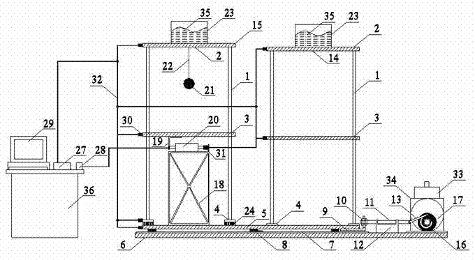
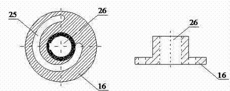
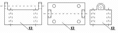
[0045] figure 1 The structure shown is the arrangement of the control frame (15) and the reference frame (14) of the same material and geometric size. The power of the motor (17) passes through the rotating force transmission rod (13), the frame force transmission rod (11), The frame connecting plate (9) is transferred to the frame connecting bottom plate (5), so as to realize the synchronous vibration of the reference frame (14) and the control frame (15) with one horizontal degree of freedom. The two water tanks (23) are respectively filled with red Body of Water (35). Horizontal vibration of different amplitudes is realized by adjusting the connecting position of the rotating force transmission rod (13) and the amplitude adjusting groove (25).
[0046] The simple pendulum mass ball (21) is connected to the upper frame plate (2) through a single cycloid (22), and the vibration control effect of the frame structure can be controlled by adjusting the length of the single cycloid...
Embodiment 2
[0048] The arrangement of the control frame (15) and the reference frame (14) structure is the same as that of the first embodiment.
[0049] Separate the column foot plate (4) of the control frame (15) with the frame connection bottom plate (5), connect the upper end of the rubber shock isolation pad (24) to the frame column (1) through the column foot plate (4), and connect the lower end to the frame connection bottom plate (5) ) Connection (the vibration control effect of the control frame structure can be achieved by increasing or decreasing the thickness of the rubber isolation pad (24)), the acceleration sensor (30) collects the reference frame (14), the control frame (15) and the frame connection base plate (5) The vibration response signal is transmitted to the charge amplifier, data acquisition and control card (27), computer and control software system (29) through the sensor signal line (32), and the collected data is displayed and analyzed, which can be visualized And...
Embodiment 3
[0051] The arrangement of the control frame (15) and the reference frame (14) structure is the same as that of the first embodiment.
[0052] One end of the magnetorheological damper (20) is connected to the magnetorheological damper bracket (18) through the force sensor (31), and the other end is connected to the lower frame plate (3) (control frame structure) through the magnetorheological damper connecting plate (19) The vibration control effect can be achieved by increasing or decreasing the current input to the magnetorheological damper (20)), the acceleration sensor (30) collects the reference frame (14), the control frame (15) and the frame connection base plate (5) The force sensor (31) collects the force signal of the magnetorheological damper (20) and transmits it to the charge amplifier and data acquisition and control card (27) through the sensor signal line (32) (the control card can be from Quanser) Q8 series of HIL control card), computer and control software syste...
PUM
 Abstract
Description
Claims
Application Information
 - R&D Engineer
- R&D Manager
- IP Professional
- Industry Leading Data Capabilities
- Powerful AI technology
- Patent DNA Extraction
Browse by: Latest US Patents, China's latest patents, Technical Efficacy Thesaurus, Application Domain, Technology Topic.
© 2024 PatSnap. All rights reserved.Legal|Privacy policy|Modern Slavery Act Transparency Statement|Sitemap