
3D (three-dimensional) protection device and 3D projection method

A projection device, 3D technology, applied in photography, stereo photography, optics, etc., can solve the problems of left and right eye signal error, difficult signal synchronization, poor focusing performance, etc., achieve optical path synchronization, compact structure, good consistency Effect

Inactive Publication Date: 2012-02-22
FUJIAN NETCOM TECH
View PDF7 Cites 9 Cited by
  • Summary
  • Abstract
  • Description
  • Claims
  • Application Information

AI Technical Summary

Problems solved by technology

[0006] Although 3D projection is realized, the overall volume is relatively large, and their optical paths projected on the screen are not synchronized, the focusing performance is poor, the pixels are low, the signals are difficult to keep in sync, and the left and right eye signal errors are prone to position deviations and other shortcomings. It is easy to make the viewer feel dizzy, which has always been a technical problem that those skilled in the art need to solve

Method used


Image

  • 3D (three-dimensional) protection device and 3D projection method
  • 3D (three-dimensional) protection device and 3D projection method
  • 3D (three-dimensional) protection device and 3D projection method

Examples


Embodiment Construction

[0033] In order to describe the technical content, structural features, achieved goals and effects of the present invention in detail, the following will be described in detail in conjunction with the embodiments and accompanying drawings.

[0034] The present invention provides a 3D projection method, comprising the following steps:

[0035] Step 1. The light source 1 emits an illumination beam;

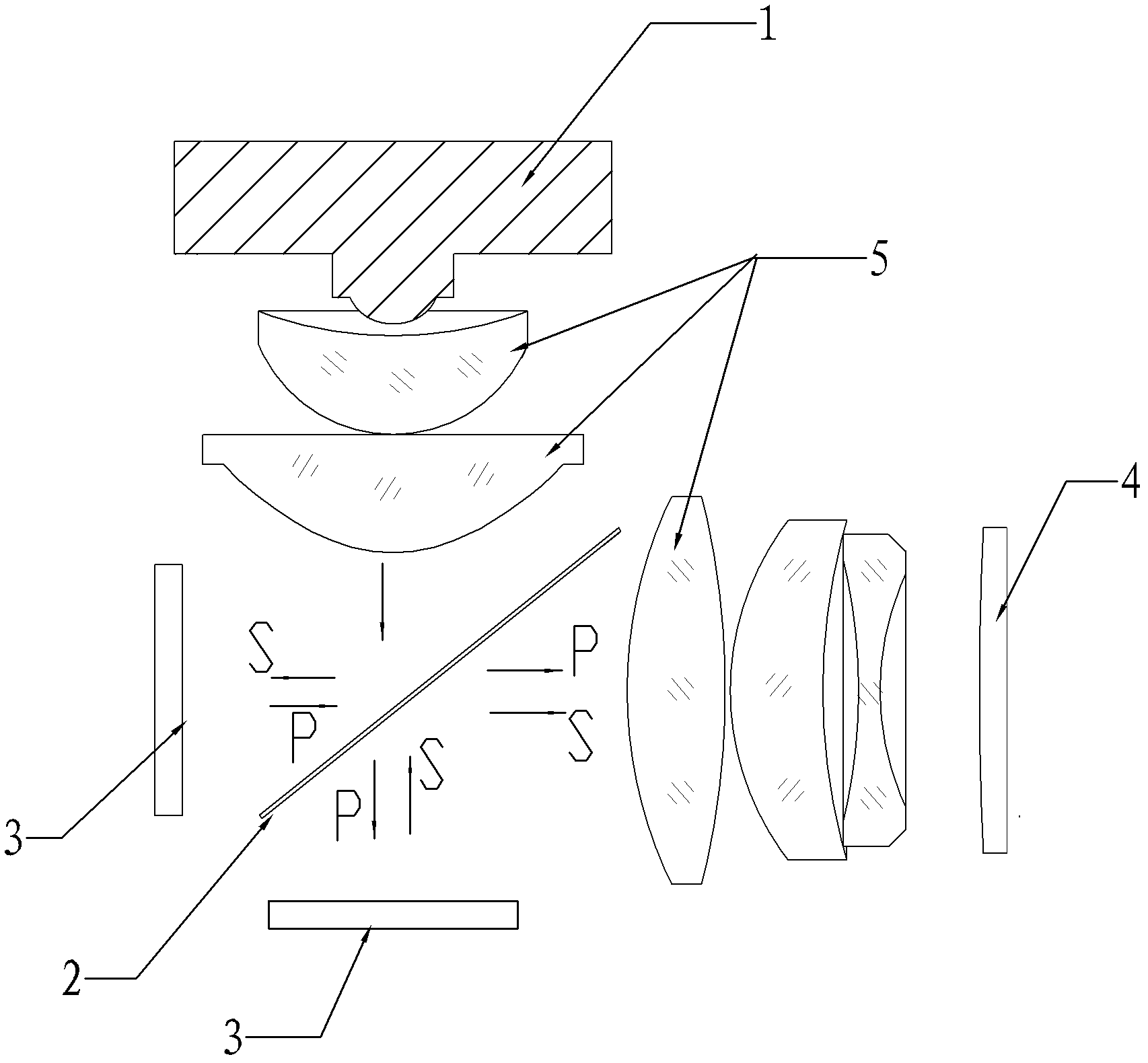
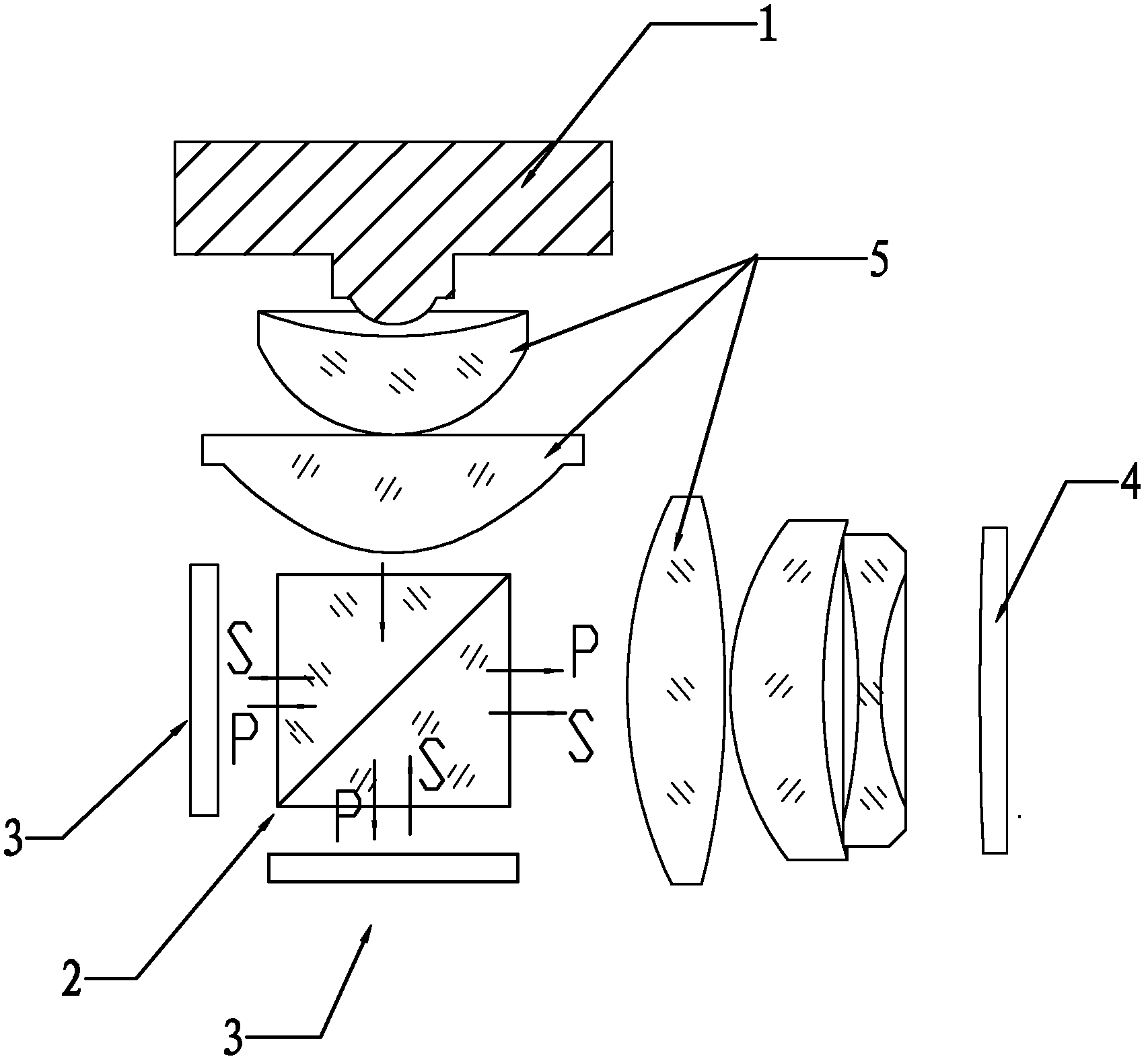
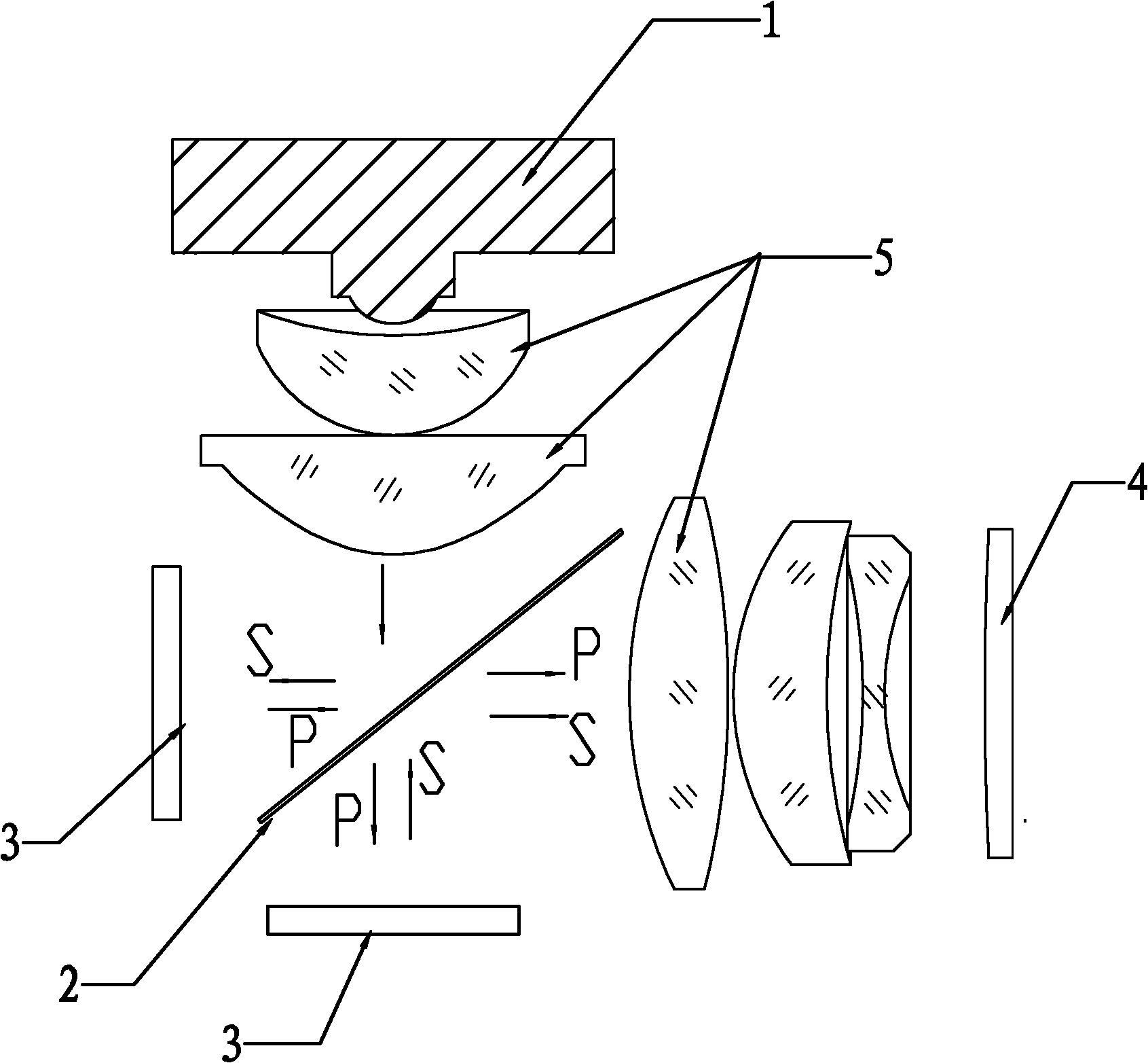
[0036] Step 2. The illumination light beam is divided into P polarized light and S polarized light whose polarization directions are perpendicular to each other through the polarization beam splitter 2, the P polarized light passes through the polarization beam splitter 2, the S polarized light is reflected, and the P polarized light and the S polarized light The beam paths are perpendicular;

[0037] Step 3. The P polarized light passes through the polarization splitting device 2 and is vertically reflected into S polarized light, and the S polarized light is vertically reflected ...


PUM


Abstract

A 3D (three-dimensional) protection device comprises a light source, a polarizing beam splitting device, two rotary liquid crystal display panels and a screen. The light source emits a beam, the polarizing beam splitting device is arranged on the path of the beam emitted by the light source and divides the beam into P polarized light and S polarized light, the polarization directions of the P polarized light and the S polarized light are perpendicular to each other, the S polarized light is reflected through the P polarized light, the beam paths of the P polarized light and the S polarized light are perpendicular to each other, the two rotary liquid crystal display panels are opposite in polarity, one rotary liquid crystal display panel is arranged on the beam path of the P polarized light, perpendicular to the beam path and used for reflecting the P polarized light into the S polarized light, the other rotary liquid crystal display panel is arranged on the beam path of the S polarized light and used for reflecting the S polarized light into the P polarized light, and the screen is used for imaging the received light. The invention aims to provide the 3D protection device and a 3D projection method, which can be used for achieving synchronism of optical distances, fine focusability, high pixel and brightness, compact structure and signal synchronization.

Description

technical field [0001] The invention belongs to the field of projection equipment, and in particular relates to a 3D projection device and a 3D projection method. Background technique [0002] With the continuous development of the display technology, the projection device has been widely used, and the development can greatly affect the effect with high image quality and high resolution. [0003] The existing 3D projection optical system is mainly to increase the refresh rate of the DLP display to above 120HZ and then realize the 3D projection function through time division. For the 3D function, two projectors, two polarizers and stereoscopic glasses are usually used at present. However, this method undoubtedly increases the cost of use. In addition, the relative position of the two projectors needs to be adjusted accurately, and after the adjustment, they cannot be moved at will. The consistency is poor, and it is very inconvenient to use. . [0004] Then there is the fun...

Claims


Application Information

Patent Timeline
Patent Type & Authority Applications(China)
IPC IPC(8): G03B35/26G02B27/26G02B27/18G02B30/25
Inventor 张嵘陈启雄林难生
Owner FUJIAN NETCOM TECH
Learn More