Unattended room temperature and humidity remote centralized control system of high-tension switch
A centralized control system and high-voltage switch technology, which is applied in the direction of control/regulation system, non-electric variable control, and simultaneous control of multiple variables, can solve the problem that whether the high-voltage switch can work normally has a great influence, and achieve the effect of simple operation
Inactive Publication Date: 2012-02-22
STATE GRID CORP OF CHINA +1
View PDF3 Cites 1 Cited by
- Summary
- Abstract
- Description
- Claims
- Application Information
AI Technical Summary
Problems solved by technology
[0002] The temperature and humidity of the unattended high-voltage switch room have a great influence on whether the high-voltage switch can work normally, and the technology of remote centralized control of the temperature and humidity of the high-voltage switch room is still blank.
Method used
View moreImage
Smart ImageViewing Examples
Examples
Embodiment Construction
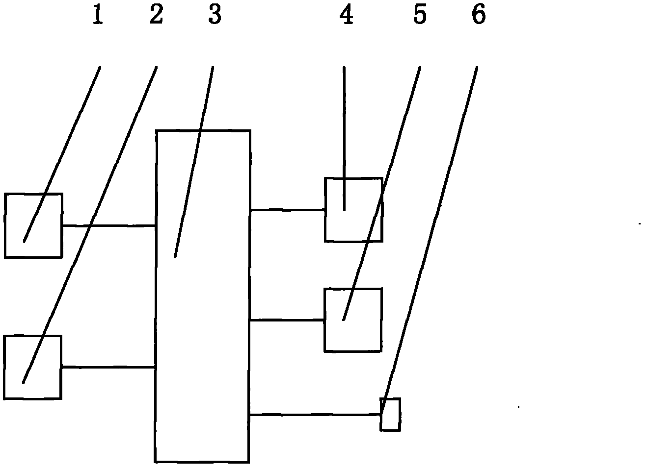
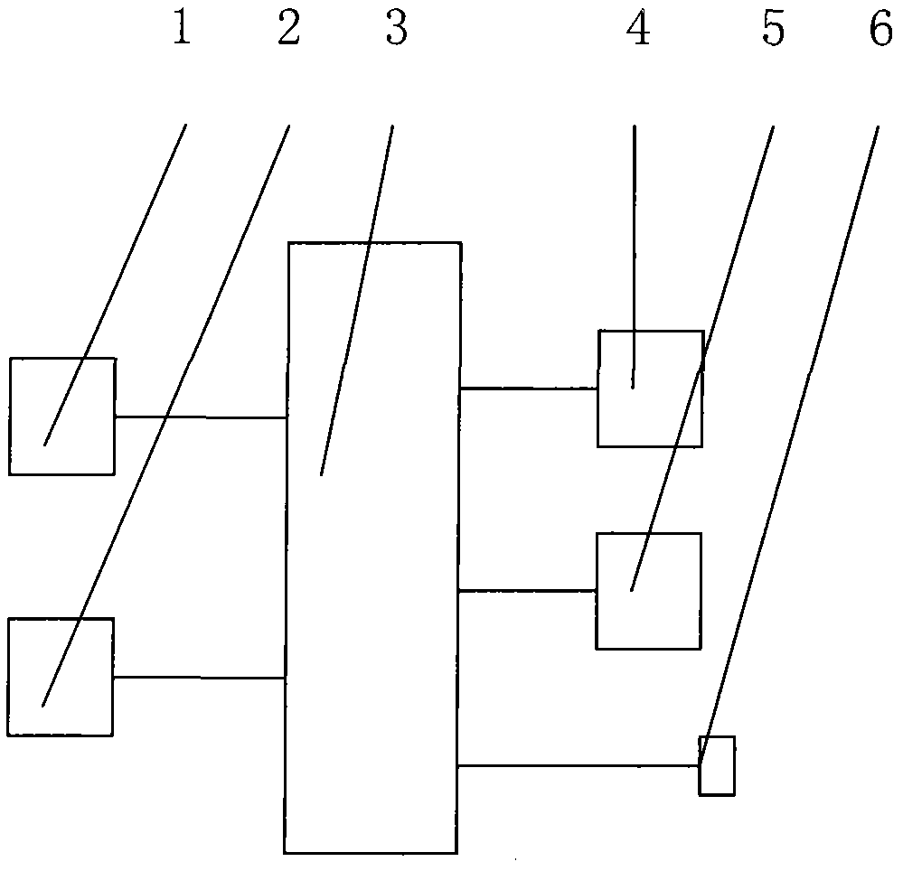
[0009] In the accompanying drawings of the specification, a temperature sensor (1), a humidity sensor (2), an air conditioner (4), a dehumidifier (5) and an Internet interface (6) are connected to the single-chip microcomputer (3) respectively.
Login to View More PUM
 Abstract
The invention relates to an unattended centralized control system of high-tension switch house, in particular to an unattended room temperature and humidity remote centralized control system of a high-tension switch, which comprises a temperature sensor, a humidity sensor, a singlechip, an air conditioner, a desiccating machine and an internet interface. The unattended room temperature and humidity remote centralized control system is characterized in that the temperature sensor, the humidity sensor, the air conditioner, the desiccating machine and the internet interface are respectively connected with the singlechip. A self-programmed program meeting the conditions are written in the singlechip. Due to the adoption of the technical scheme, the invention has the advantages of simpleness in operation, convenience and practicability.
Description
technical field [0001] The invention relates to a centralized control system for an unattended high-voltage switch room, in particular to a remote centralized control system for room temperature and humidity of an unattended high-voltage switch. Background technique [0002] The temperature and humidity of the unattended high-voltage switch room have a great influence on whether the high-voltage switch can work normally, and the technology of remote centralized control of the temperature and humidity of the high-voltage switch room is still blank. Contents of the invention [0003] The technical problem to be solved by the present invention is to provide a remote centralized control system for room temperature and humidity of an unattended high-voltage switchgear, which can perform remote centralized control of the temperature and humidity of an unattended high-voltage switchgear room. [0004] The technical scheme adopted by the present invention to solve its technical pr...
Claims
Login to View More Application Information
Patent Timeline
 IPC IPC(8): G05D27/02
Inventor 刘广勇王萍
Owner STATE GRID CORP OF CHINA
- R&D Engineer
- R&D Manager
- IP Professional
- Industry Leading Data Capabilities
- Powerful AI technology
- Patent DNA Extraction
Learn More Browse by: Latest US Patents, China's latest patents, Technical Efficacy Thesaurus, Application Domain, Technology Topic, Popular Technical Reports.
© 2024 PatSnap. All rights reserved.Legal|Privacy policy|Modern Slavery Act Transparency Statement|Sitemap|About US| Contact US: help@patsnap.com


