Device for processing and positioning engine shell

A technology for engine casings and positioning devices, applied in positioning devices, metal processing equipment, metal processing machinery parts, etc., can solve problems affecting work efficiency, complicated alignment process, and long operating time

Inactive Publication Date: 2012-02-29
WEICHAI POWER CO LTD
View PDF5 Cites 8 Cited by
  • Summary
  • Abstract
  • Description
  • Claims
  • Application Information

AI Technical Summary

Problems solved by technology

The shortcomings of the traditional engine housing processing and positioning device are: 1. Due to the use of bolt positioning and locking, the operation time is long, which affects the work efficiency
2. Before inserting the bolts, you need to align the mounting holes and positioning holes. The alignment process is complicated and will affect work efficiency

Method used


Image

  • Device for processing and positioning engine shell
  • Device for processing and positioning engine shell
  • Device for processing and positioning engine shell

Examples


Embodiment Construction

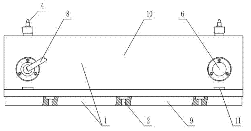
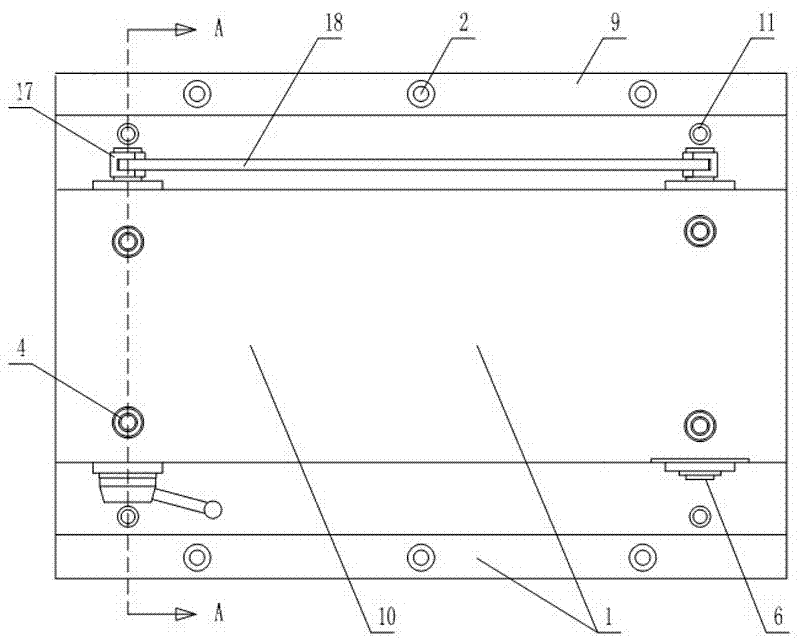
[0017] Such as figure 1 , figure 2 As shown, the engine housing processing positioning device includes a positioning platform 1, and the positioning platform 1 is provided with an inner cavity. Six fixing holes 2 are evenly distributed on the bottom side of the positioning table 1, and the fixing holes 2 are set correspondingly to the positions of the T-shaped slots of the machine tool workbench. Two rows of pinholes 3 are arranged on the upper end surface of the housing, and the pinholes 3 are arranged corresponding to the positions of the positioning holes on the engine housing. In this embodiment, the number of pinholes 3 is four. A positioning pin 4 is inserted in each pin hole 3, and the positioning pin 4 is cylindrical, and the positioning pin 4 is axially slidingly matched with the pin hole 3, and the positioning pin 4 upper ends are tapered with a small upper end and a large lower end. A sliding sleeve 20 is also sleeved on the outside of the positioning pin 4 , and...


PUM


Abstract

The invention discloses a device for processing and positioning an engine shell. The device comprises a positioning table which is provided with an inner cavity, wherein the edge of the positioning table is provided with fixing holes which is in installation fit with a machine tool workbench; the upper end face of the shell is provided with two rows of pin holes which correspond to the positioning holes on the engine shell; positioning pins are inserted into the pin holes in a sliding way; the upper ends of the positioning pins are conical; the middle part of the positioning table is providedwith a driving mechanism for driving the positioning pins to ascend and descend simultaneously; the driving mechanism comprises a main revolving shaft and a secondary revolving shaft which are horizontally arranged on the middle part of the positioning table at a certain interval; shifting forks which are in transmission fit with the lower ends of a first row of positioning pins and a second row of positioning pins are arranged on the main revolving shaft and the second revolving shaft respectively; a crank is fixedly arranged at one end of the main revolving shaft; swinging arms which are arranged at the same angle are arranged at the other end of the main revolving shaft and a corresponding end of the auxiliary revolving shaft; and tail ends of the two swinging arms are connected together through a connecting rod. The device for processing and positioning the engine shell has a reasonable structure, is simple to align, is rapid for positioning, is convenient to operate, and has contribution to increasing the working efficiency.

Description

technical field [0001] The invention relates to a processing and positioning device for an engine casing. Background technique [0002] An engine, also known as an engine, is a machine that can convert other forms of energy into another energy, usually chemical energy into mechanical energy. Taking a diesel engine as an example, a diesel engine mainly includes a housing, a cylinder, a piston, a crankshaft and other related components. Among them, the engine casing is the carrier for all other components. Therefore, the structural strength and machining accuracy of the engine casing seriously affect the overall performance of the engine. When the engine casing is being processed, the engine casing is generally positioned first. Due to the irregularity of the engine shell structure, it is not only very troublesome to directly fix the engine shell on the machine tool table, but the key point is that every time a shell is replaced, the coordinate zero point needs to be re-dete...

Claims


Application Information

Patent Timeline
Patent Type & Authority Applications(China)
IPC IPC(8): B23Q3/06
Inventor 刘国千刘春晖刘建国
Owner WEICHAI POWER CO LTD
Why Eureka
Try Eureka