
Storage battery lift truck driving motor braking apparatus

A technology for driving motors and braking devices, applied in the direction of electromechanical devices, electric components, electrical components, etc., can solve the problems of lowering the working efficiency of lift trucks, prone to overshooting, and difficult installation of motors, so as to save manpower and improve work efficiency , the effect of simple structure

Active Publication Date: 2012-02-29
江苏金帆电源科技有限公司
View PDF5 Cites 0 Cited by
  • Summary
  • Abstract
  • Description
  • Claims
  • Application Information

AI Technical Summary

Problems solved by technology

In this process, due to the influence of factors such as the weight of the battery and the speed change of the lift car, it is difficult for the motor 5 to stop accurately, and overshooting is prone to occur (the amount of overshooting can reach 10-40 mm).
It is necessary to manually adjust the position of the switch and reduce the running speed of the motor 5 to correct it, which not only causes a lot of waste of manpower, but also greatly reduces the working efficiency of the lift truck.

Method used


Image

  • Storage battery lift truck driving motor braking apparatus
  • Storage battery lift truck driving motor braking apparatus
  • Storage battery lift truck driving motor braking apparatus

Examples


Embodiment Construction

[0012] The braking device for driving the motor of the battery lift car of the present invention will be further described in detail through specific embodiments below.

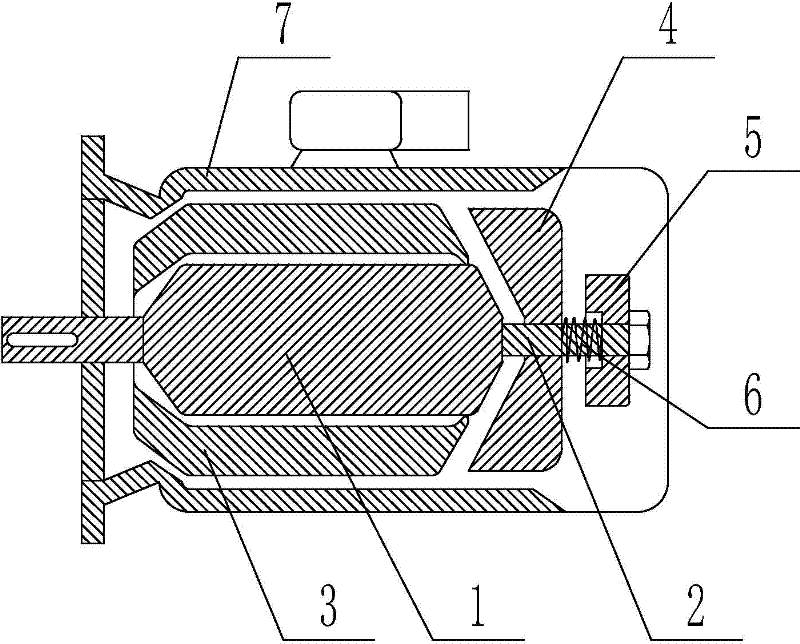
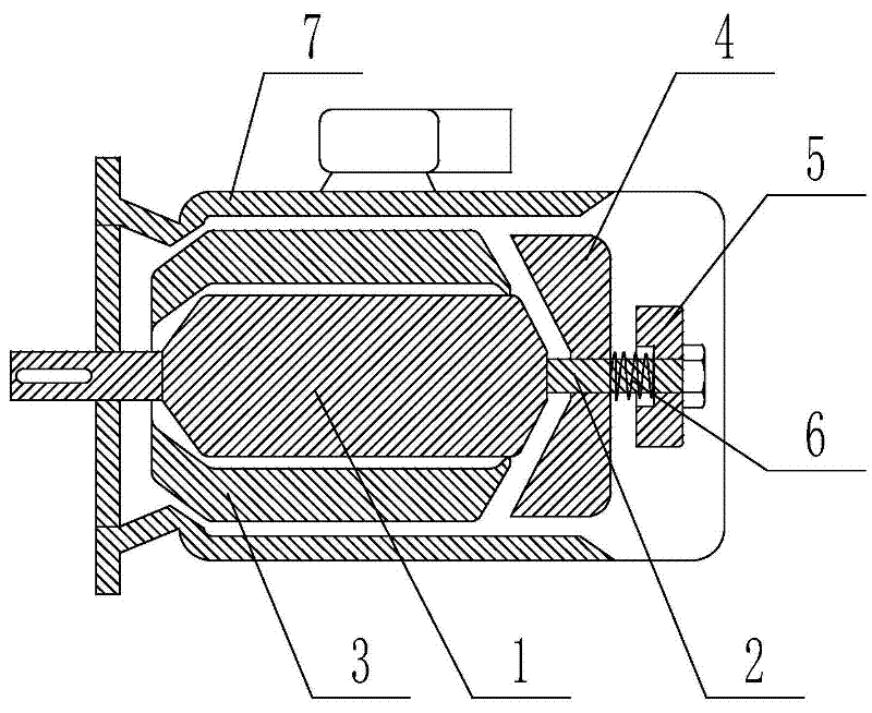
[0013] like figure 1 As shown, the motor brake device driven by the battery lift car includes an elongated shaft 2 arranged at the rear end of the rotor 1 of the motor and a stator 3 sleeved outside the rotor 1 of the motor. The elongated shaft 2 is sequentially provided with cones Shaped iron 4 and electromagnet 5, spring 6 is arranged between conical iron 4 and electromagnet 5, and described extension shaft 2, stator 3, conical iron 4, electromagnet 5 and spring 6 are all arranged on the motor Shell 7.

[0014] The working principle of the present invention is: when the motor is energized and needs to run, the electromagnet 5 is energized to generate magnetism to absorb the conical iron 4. At this time, the spring 6 is in a compressed state, and the stator 3 rotates synchronously with the rotor 1 of the m...


PUM


Abstract

The invention relates to a storage battery lift truck driving motor braking apparatus. The apparatus comprises an extending shaft which is arranged on a rear end of a rotor of the motor and a stator which is sleeved on outside of the rotor of the motor. Tapered iron and an electromagnet are successively arranged on the extending shaft. A spring is arranged between the tapered iron and the electromagnet. The storage battery lift truck driving motor braking apparatus of the invention can be applied in the driving motor of the storage battery lift truck. By using the apparatus, the driving motorof the storage battery lift truck can stop accurately.

Description

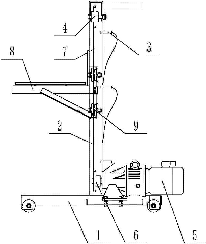
technical field [0001] The invention relates to the technical field of storage battery production equipment, in particular to a braking device for a driving motor of a storage battery lift vehicle. Background technique [0002] At present, in the production process of batteries, in order to save labor, most of the transportation of batteries is carried by automatic chain plates or power rollers. When the battery is transported to a designated position, the battery is manually pushed into the lift car, automatically lifted to a certain height, and the motor of the lift car is stopped by sending a signal through the photoelectric switch or travel switch, so that the lift car is positioned at a specified position. height, and then manually push the battery out of the lift car to complete a change in the height of the battery. [0003] The structure of the battery lift car is as follows: figure 2 As shown, including a frame 1, a lifting frame 2 is arranged on the frame 1, seve...

Claims


Application Information

Patent Timeline
Patent Type & Authority Applications(China)
IPC IPC(8): H02K7/10
Inventor 彭正雄朱新华
Owner 江苏金帆电源科技有限公司
Learn More