frequency synthesizer

A frequency synthesizer, the technology of outputting frequency, applied in the direction of automatic power control, electric pulse generator circuit, pulse generation, etc., to achieve the effect of improving energy efficiency and low sensitivity

Active Publication Date: 2017-06-27
NXP BV
View PDF4 Cites 0 Cited by
  • Summary
  • Abstract
  • Description
  • Claims
  • Application Information

AI Technical Summary

Problems solved by technology

[0015] However, the problem with burst-mode PLLs is that it requires a specific architecture for stability during the transition between active and idle cycles, as well as a fast start-up circuit to avoid additional power consumption

Method used


Image

  • frequency synthesizer
  • frequency synthesizer
  • frequency synthesizer

Examples


Embodiment Construction

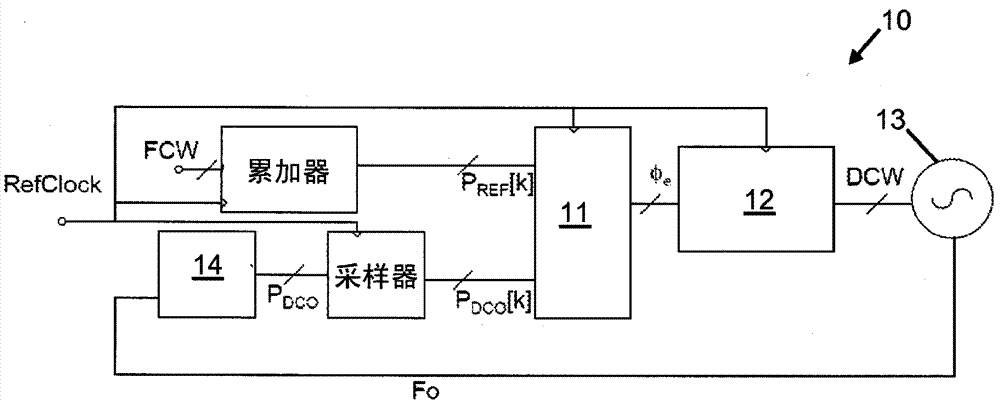
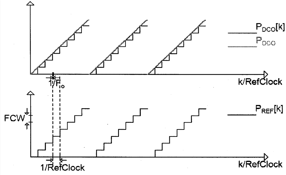
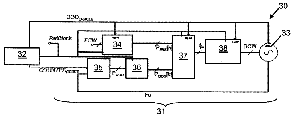
[0058] The object of the invention is to generate a pulse train with a fixed time width and a center frequency locked to a reference clock frequency (RefClock), typically a multiple of the reference clock frequency. image 3 A schematic block diagram of an example frequency synthesizer 30 is depicted, comprising a phase domain all digital frequency locked loop (ADFLL) 31 and a finite state machine (FSM) 32 as a duty cycle module. All blocks in ADFLL 31 are gated to minimize power consumption between generation of two consecutive IR pulses. With proper synchronization, the stability of the feedback loop is maintained and the output frequency of the DCO33 is locked to the stable reference frequency input RefClock with low power consumption.

[0059] In general, the frequency synthesizer circuit 30 includes a feedback loop 31 having counter modules 35, 36 and phase difference modules 34, 37, the counter modules 35, 36 being configured to, when the digitally controlled oscillator ...


PUM


Abstract

A low-power frequency synthesizer circuit (30) for a radio transceiver, the synthesizer circuit comprising: a digitally controlled oscillator (33), configured to generate an output signal (F0) having a frequency, input by a digital control word ( DCW) to control the frequency; a feedback loop (35‑38) connected between the output and input of the digitally controlled oscillator, configured to provide a digital control word to the input of the digitally controlled oscillator, the digital control word coming from the slave input frequency control word (FCW) and the error obtained in the output signal; and a duty cycle module (32) connected to a digitally controlled oscillator and a feedback loop, configured to generate a plurality of control signals to vary between input reference clock signals (RefClock) Sets a fraction of the clock period to periodically enable and disable the digitally controlled oscillator.

Description

technical field [0001] The present invention relates to digital phase locked loop circuits for use as frequency synthesizers such as in ultra low power (ULP) pulse based radio transceivers. Background technique [0002] The architecture of a down-converting RF receiver requires a frequency synthesizer to convert the received RF signal to lower frequencies where channel filtering can be achieved with a low-pass (low-Q) filter. Frequency synthesizers can also be used to up-convert baseband information to RF frequencies in wireless communications. Synthesizers in RF transceivers must be able to provide a clean (i.e., low noise) frequency signal with very high absolute accuracy over the expected range of process voltage temperature (PVT) variations, and are typically the most power-hungry components in transceivers. module. [0003] In impulse radio (IR) based transceivers, especially in the context of low data rate ultra-low power (ULP) radios, the transmitted signal consists...

Claims


Application Information

Patent Timeline
Patent Type & Authority Patents(China)
IPC IPC(8): H03K3/03H03L7/08H03L7/099
CPCH03K3/012H03K3/0322H03L7/0802H03L7/087H03L7/0995H03L7/103H03L7/107H03L7/18H03L2207/06H03L2207/50
Inventor 萨尔瓦托·德拉戈法比奥·塞巴斯蒂亚诺多米尼克斯·马蒂纳斯·威廉默斯·莱纳特吕西安·约翰内斯·布伦默斯布拉姆·诺塔
Owner NXP BV
Why Eureka
Try Eureka