
Fast lead-out device and method of oil gas for restraining coking in heavy oil catalytic cracking settler

A heavy oil catalysis and settler technology, applied in the direction of catalytic cracking, treatment equipment corrosion/fouling inhibition, cracking, etc. Equipment fluctuation and other problems

Active Publication Date: 2012-03-14
CHINA PETROLEUM & CHEM CORP +1
View PDF14 Cites 5 Cited by
  • Summary
  • Abstract
  • Description
  • Claims
  • Application Information

AI Technical Summary

Problems solved by technology

According to this patent scheme, although it can be realized that the stripped oil and gas at the bottom of the settler can be quickly exported to the settler, the position of the oil and gas extraction inlet of the draft tube-diffuser and the discharge outlet of the secondary cyclone separator is too close. Therefore, no matter whether the material leg of the secondary separator is wrapped in the shroud or not, the finer catalyst particles discharged from the secondary cyclone separator are likely to be sucked into the draft tube along with the oil and gas, and then enter the secondary cyclone separator. The first-stage cyclone separator increases the load of the second-stage cyclone separator, the catalyst loss, and the solid content of the oil slurry; the higher the flow rate in the draft tube and the greater the suction force, the more serious the catalyst loss
In addition, this patented solution also has defects such as poor ability to resist device fluctuations (pressure, flow, catalyst storage, etc.)
Once the material level in the stripping section rises, a large amount of catalyst is easily sucked into the draft tube, resulting in an increase in the solid content of the oil slurry

Method used


Image

  • Fast lead-out device and method of oil gas for restraining coking in heavy oil catalytic cracking settler
  • Fast lead-out device and method of oil gas for restraining coking in heavy oil catalytic cracking settler
  • Fast lead-out device and method of oil gas for restraining coking in heavy oil catalytic cracking settler

Examples


Embodiment Construction

[0041] For a clearer understanding of the technical content of the present invention, an embodiment is given below for detailed description:

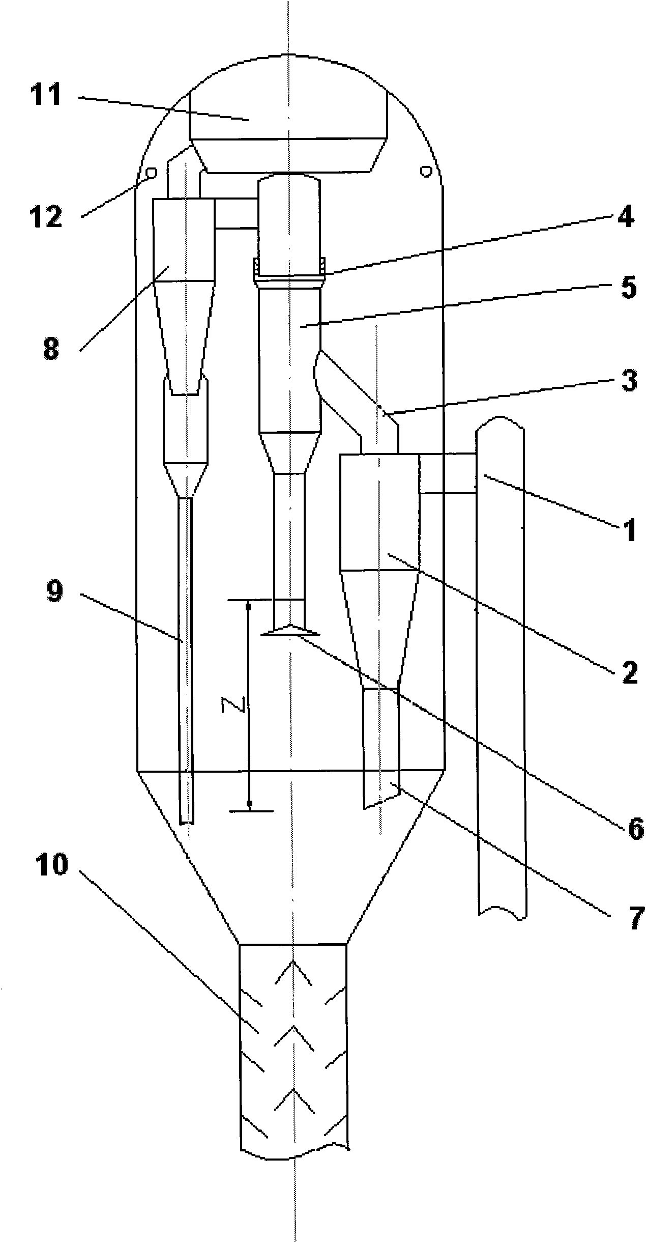
[0042] figure 1 According to the idea of ​​the present invention, it is an embodiment of rapid extraction of oil and gas for suppressing coking in a settler. 1 is the inlet section of the coarse cyclone separator at the end of the riser reactor; 2 is the air separator of the coarse cyclone separator, and one or more coarse cyclone separators can be connected in parallel; 3 is the connection between the air riser and the oil and gas drainage pipe of the coarse cyclone separator Connecting pipe; 4 is a socket-type soft connection between the upper and lower parts of the oil and gas drainage pipe; 5 is the oil and gas drainage pipe, the lower part of which is open to the settlement space, and the upper part is airtightly connected to the inlet of the top cyclone separator; there can be one or more oil and gas drainage pipes; But it is pre...


PUM


Abstract

The invention discloses a fast lead-out device and method of oil gas for restraining coking in a heavy oil catalytic cracking settler. The device comprises a rough cyclone separator (2) in the settler, a top cyclone separator (8), an oil gas drain tube (5) and a steam stripping section (10) arranged at the bottom of the settler, characterized in that: an opening at the bottom of the oil gas drain tube (5) is arranged more highly than a discharge port of a dip leg (2) of the rough cyclone separator (2) and simultaneously more highly than a discharge port of a dip leg (9) of the top cyclone separator (8), and the height difference of the latter is larger than the splashing height of the catalyst discharged from the dip leg (2) of the rough cyclone separator (2). The use of the invention can rapidly separate the oil gas from the catalyst, the oil gas enters in the space of the settler and is rapidly discharged, thus the diffusion of the oil gas to the all space of the settler can be avoided, the coking caused by long-time retention of the oil gas in the space of the settler can be eliminated, and the working period of the device can be prolonged.

Description

technical field [0001] The invention relates to the technical field of petrochemical industry, related to oil refining and chemical technology and its equipment, in particular to a method and equipment for quickly extracting oil and gas to suppress coking in a heavy oil catalytic settler. Background technique [0002] Catalytic cracking (FCC) is the most important secondary processing process in my country's oil refining industry. Its purpose is to improve the crude oil processing depth and product quality, and increase the output of light oil. With the continuous development of catalytic cracking process and catalyst technology, catalytic cracking feed oil has been expanded to atmospheric residue and vacuum residue. The heavy oil feedstock has led to increasingly serious and common coking problems on the surface of equipment in the reaction settler system, oil and gas pipelines, fractionation tower bottoms, and oil slurry systems of heavy oil catalytic cracking units, and h...

Claims


Application Information

Patent Timeline
IPC IPC(8): C10G75/00C10G11/00
Inventor 孙国刚吴雷付烜时铭显李华范声阎涛杨启业卢松坚
Owner CHINA PETROLEUM & CHEM CORP
Learn More