Roller for a paper and/or carton machine

A technology of cardboard machine and paper machine, applied in paper machine, paper making, textile and paper making, etc., can solve the problem of low shock absorption efficiency and so on

Inactive Publication Date: 2012-03-14
VOITH PATENT GMBH
View PDF5 Cites 0 Cited by
  • Summary
  • Abstract
  • Description
  • Claims
  • Application Information

AI Technical Summary

Problems solved by technology

But at high frequencies such as 150 ...

Method used


Image

  • Roller for a paper and/or carton machine
  • Roller for a paper and/or carton machine
  • Roller for a paper and/or carton machine

Examples


Embodiment Construction

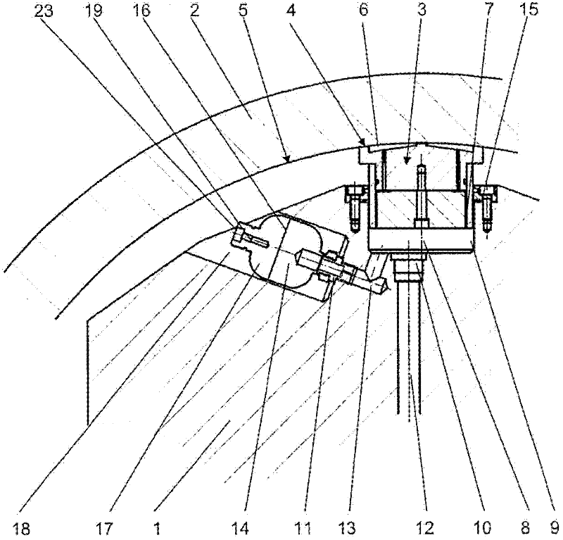
[0027] figure 1 A partial cross-section of a roller with a fixed support 1 and a surrounding roller sleeve 2 is shown. The bracket 1 penetrates the roller sleeve 2 axially here. The sleeve 2 is pressed radially outward by means of the supporting element 3. For this purpose, the support element 3 rests with the contact side 4 on the inner side 5 of the roller sleeve 2. The support element 3 has a pressure chamber 6 on its contact side 4, in which pressure chamber contains oil for forming an oil film between the contact side 4 and the inner side 5.

[0028] The support element 3 is guided in the pressure chamber 8 in a radially movable manner by a cylindrical projection 7. The pressure chamber 8 is connected to a pressure medium pipe 12 via a throttle 10, which is guided outward through the support 1 and used to provide the pressure chamber 8 with a pressure medium under pressure, such as pressure fluid.

[0029] The position of the support element 3 or the support 1 is determined...


PUM


Abstract

The present invention relates to a roller for a paper and/or carton machine. The roller comprises a rotating roller shell (2), and a stationary yoke (1), which axially passes through the roller shell (2). The roller shell is loaded by the pressure in a pressure chamber (8) radially outwards. The pressure chamber is connected with a pressure medium line (12) by a throttle point (10). The pressure chamber (8)is connected weith a pressure space (14) via a channel (13). The pressure space (14) has a variable volume. In order to realize excellent anti-shock effect when the frequency is high, the pressure space (14) has a maximum volume of 0.025 to 0.16 liters, and the channel (13) has another throttle (11).

Description

Technical field [0001] The present invention relates to a roller especially used in a paper machine or a paperboard machine. The roller has a surrounding roller sleeve and a fixed support or a fixed yoke extending axially through the roller sleeve, wherein the roller sleeve is subjected to pressure in at least one pressure chamber The pressure chamber can bear the load radially outwards, and the pressure chamber is connected to the pressure medium pipeline through the throttling point, and the pressure chamber is connected to at least one pressure space through at least one passage, and the at least one pressure space has a variable volume. Background technique [0002] This roller is used as a bending compensation roller, a wandering roller or a shoe press roller to form a nip with the counter roller. A fibrous web, generally a paper web or a cardboard web, is guided through the nip and is loaded in the nip with increased pressure and, if necessary, increased temperature. [0003...

Claims


Application Information

Patent Timeline
IPC IPC(8): D21G1/02
CPCF16C13/028D21G1/008D21G1/022
Inventor R.范哈格
Owner VOITH PATENT GMBH
Why Eureka
Try Eureka