Supercharge Your Innovation With Domain-Expert AI Agents!

Buoyancy and gravity circulating electricity generation method

A technology of gravity circulation and buoyancy, applied in hydroelectric power generation, engines, engine components, etc.

Inactive Publication Date: 2012-03-14
张效琪
View PDF0 Cites 20 Cited by
  • Summary
  • Abstract
  • Description
  • Claims
  • Application Information

AI Technical Summary

Problems solved by technology

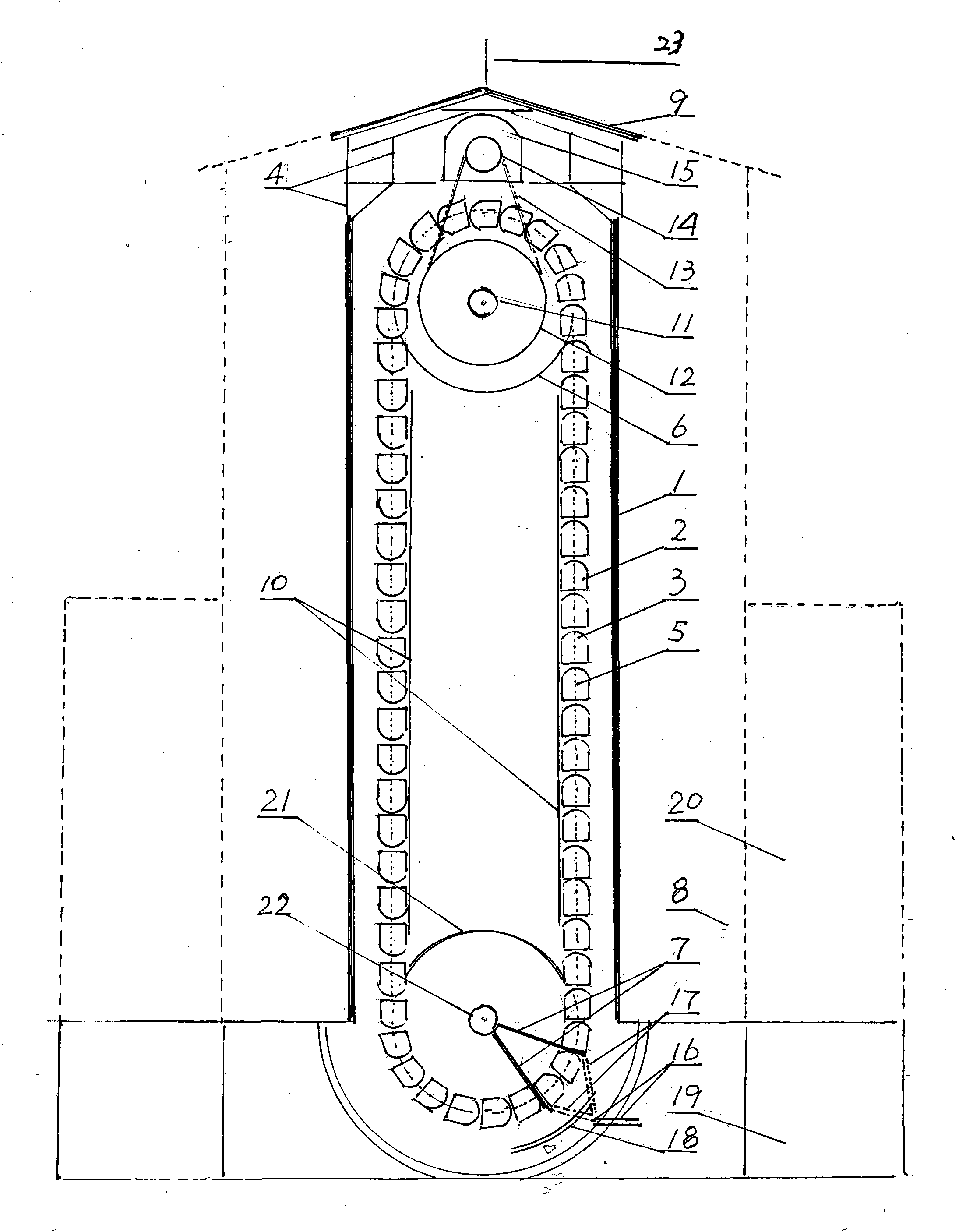
[0030] When the buoyancy and gravity box reach their peaks—the top of the buoyancy water tower enters the turnover cycle tower for cyclical steering, and then turns to descend, the weight of the gravity box begins to generate gravitational potential energy and exert energy. This gravity box that generates gravitational potential energy The weight, speed, distance and overall quantity and weight determine the output power and the size of the power generation capacity. Also, the same amount of air is injected, the longer the distance it rises in the buoyancy water tower, the lower the relative gravity object The longer the distance is, this is the principle of 'the product of force and path is equal to work', 'the longer the path, the more work done, the more work the same force walks, the more work done', but everything has a degree of problem, Due to the problem of air pressure and volume, the height of the buoyancy water tower, the pressure of the injected air, and the volume of the buoyancy tank are better. Which one is more reasonable and economical? There is more waste and less shortage. There is a comprehensive evaluation. coefficient, which also determines the design and construction requirements for the height of the buoyancy water tower

Method used


Image

  • Buoyancy and gravity circulating electricity generation method
  • Buoyancy and gravity circulating electricity generation method
  • Buoyancy and gravity circulating electricity generation method

Examples


specific Embodiment approach 1

[0108] Specific implementation mode one, the implementation mode of building buoyancy water tower:

[0109] The capacity of the buoyancy water tower, namely diameter and height, and the water capacity of the buoyancy water tower are the basis for implementing buoyancy energy creation. In order to accommodate larger buoyancy tanks and float heavier gravitational objects, first of all, there must be a large volume of water. If the buoyancy tank and gravity objects are lifted to an ideal height, the height of the buoyancy water tower must also reach the ideal height. Therefore, the height of the buoyancy water tower initially designed by the present invention is 100 meters to 150 meters or more, and the shape is square or rectangular, and the inner diameter is: long × wide, that is, 50 × 50 meters or 60 × 50 meters, and even 80 × 80, 80×100 meters or more, etc., the volume cavity in the tower should be 20-30 meters deep underground to facilitate the sinking and stability of the b...

specific Embodiment approach 2

[0110] Specific implementation mode two, the implementation mode of the large buoyancy box:

[0111] The buoyancy box is the driving force for generating buoyancy. To float a large gravity object, its buoyant volume must match the weight tonnage of the gravity box. To achieve buoyancy, the buoyancy volume must be added, plus The weight of the upper packaging and other associated weights will at least increase the buoyancy energy volume of more than 40%-50%, so the weight ratio of the air volume of the buoyancy box to the gravity box should be 1.4:1-2,0: Between 1 or above, the buoyancy cycle power generation method is calculated according to the requirements of the buoyancy water tower model with a height of 130-180 meters or above-this is for the convenience of calculation, not a fixed formula, because the present invention can be large or small, and it is impossible to have limitations of.

[0112] 1. The buoyancy and gravity cycle power generation buoyancy and gravity boxe...

specific Embodiment approach 3

[0118] Specific embodiment three, the embodiment of the gravity box:

[0119] 1. The material of the gravity body: it should be mainly stone with large specific gravity or heavy metals such as iron, lead, etc. It is the carrier of weight, but the specific gravity is small in size. The specific gravity of granite is 3-5, the specific gravity of volcanic rock is 2-4, and the specific gravity of iron The specific gravity is 7.86, and the specific gravity of lead is 11.3, so the gravity box material with a weight of 30 tons needs 6-10 cubic meters of rock, or 3,82 cubic meters of iron, or 2,66 cubic meters of lead, and the input cost is based on stone. The lowest, the highest is lead metal, and the iron is in the middle. Of course, the smaller the volume, the better the effect.

[0120] 2. The combination of the gravity box and the buoyancy box is an ideal combination. The gravity object can be at the front end of the buoyancy box, or in the middle of the buoyancy box, or it can b...


PUM

PropertyMeasurementUnit
Heightaaaaaaaaaa

Abstract

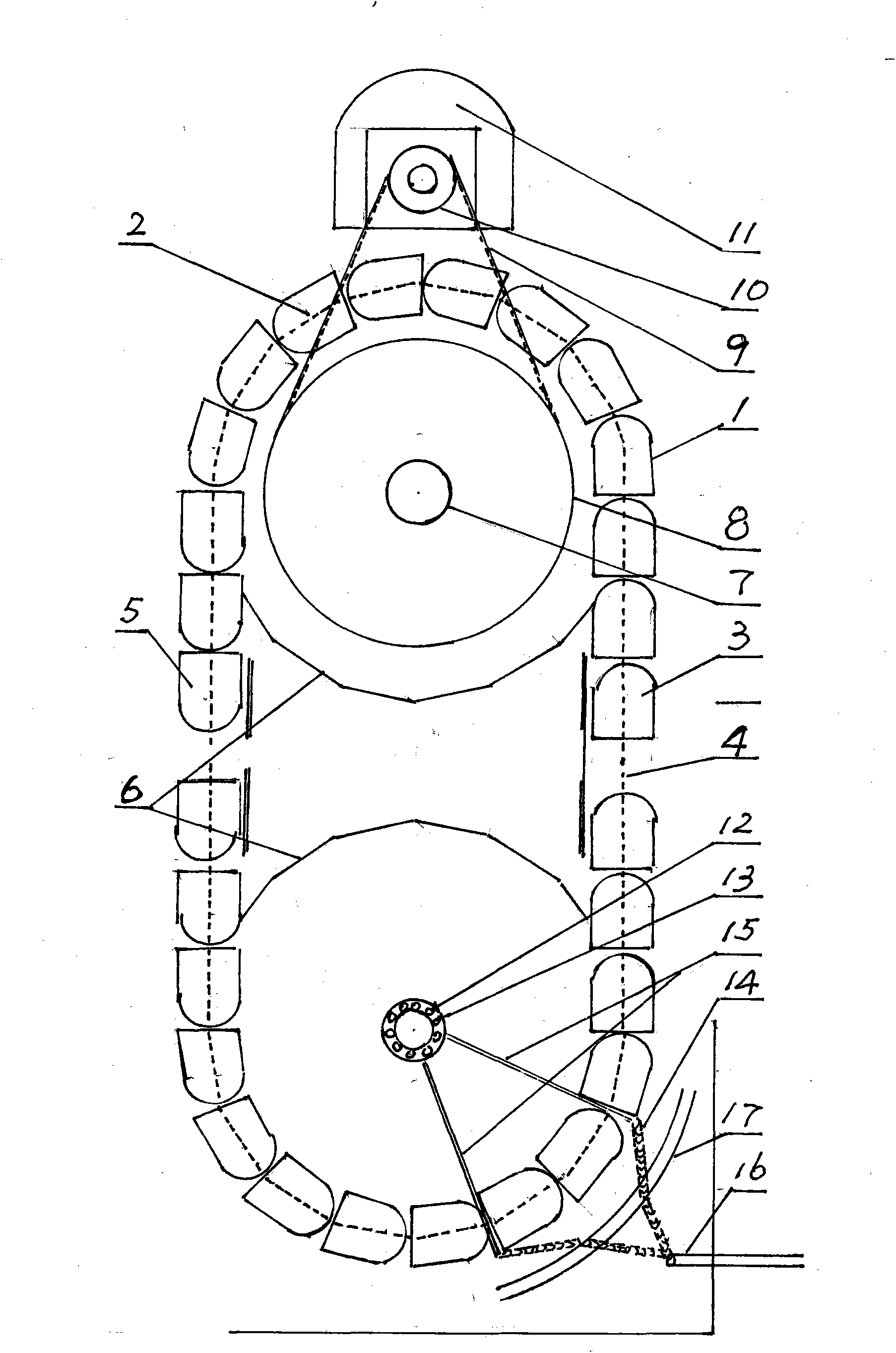
The invention relates to a buoyancy and gravity circulating electricity generation method and relates to a method utilizing the buoyancy and gravity in a buoyancy water tower to create mechanical energy so as to generate electricity for the first time. The electricity generation method is characterized in that a plurality of buoyancy and gravity circulating chains 5 are made of multiple materials, are chained and consist of more than ten buoyancy boxes 3 and gravity boxes 2 in a buoyancy water tower 1 filled with water, a gas injection hosepipe is arranged between two steering wheel bodies 6 of a support tower 4, restrained by a dragging track 10 and controlled by a mechanical arm 7 on the swerving ascending position of the lower steering wheel body, a driving shaft body 11 is connected with a gas supply line 12, an underground pressure air storage warehouse 13 and an overground pressure air storage warehouse 19 which are used for injecting gas into a buoyancy box successively so as to carry gravity things to rise to form buoyancy energy, the buoyancy energy is swerved through steering wheels so as to drive a main driving shaft body 14 to drive a driving wheel body 15, a driving chain 16 is used for driving a speed-regulating box 17 to drive a generator 18 to generate electricity, a vacancy 8 is a reserved large-scale pressing machine or high-pressure air pressure air-containing tower position.

Description

Technical areas: [0001] The invention relates to a new power generation method, which is a pioneering buoyancy and gravity cycle power generation method in the field of electricity. It is a kind of buoyancy generated by continuously injecting air into the buoyancy box at the bottom of the buoyancy and gravity turnover cycle chain in the buoyancy water tower to continuously lift the gravity objects integrated with the buoyancy box to the buoyancy water tower. The power generation method of a continuous cycle in which the top is turned downward and converted into gravitational potential energy, and then into mechanical energy to generate electricity, is referred to as the buoyancy and gravity cycle power generation method. Background technique: [0002] Since the invention of power generation technology, the energy materials used in power generation have been as follows: [0003] 1. It is thermal energy resources accumulated on the earth for hundreds of millions of years, suc...

Claims


Application Information

Patent Timeline
IPC IPC(8): F03B17/02F03G3/00
CPCY02E10/20
Inventor 张效琪
Owner 张效琪
Features
  • R&D
  • Intellectual Property
  • Life Sciences
  • Materials
  • Tech Scout
  • Unparalleled Data Quality
  • Higher Quality Content
  • 60% Fewer Hallucinations
Learn More