
Method and device for measuring equal precision frequency of single coil vibrating wire instrument

A technology of frequency measurement and equal precision, applied in measurement devices, instruments, electrical devices, etc., can solve the problems of inability to complete the measurement and reduce the measurement accuracy, and achieve the effect of simple and feasible measurement method, improved reliability, and easy operation.

Active Publication Date: 2013-01-16
CHINA GEOKON INSTR
View PDF0 Cites 0 Cited by
  • Summary
  • Abstract
  • Description
  • Claims
  • Application Information

AI Technical Summary

Problems solved by technology

[0006] The present invention is aimed at the equal-precision frequency measurement method of the existing single-coil vibrating-wire instrument. In different operating stages, the duration of the induced electromotive force generated by the excitation of the single-coil vibrating-wire instrument has a large difference, resulting in inability to To solve the problem of completing the measurement or reducing the measurement accuracy, a method for measuring the frequency with equal precision of a single-coil vibrating wire instrument is proposed. Value attenuation, adaptively adjust the duration of the measurement process, and maintain the same measurement accuracy, improving the reliability of frequency measurement of single-coil vibrating wire instruments

Method used


Image

  • Method and device for measuring equal precision frequency of single coil vibrating wire instrument
  • Method and device for measuring equal precision frequency of single coil vibrating wire instrument
  • Method and device for measuring equal precision frequency of single coil vibrating wire instrument

Examples


Embodiment Construction

[0032] The present invention will be described below in conjunction with the accompanying drawings.

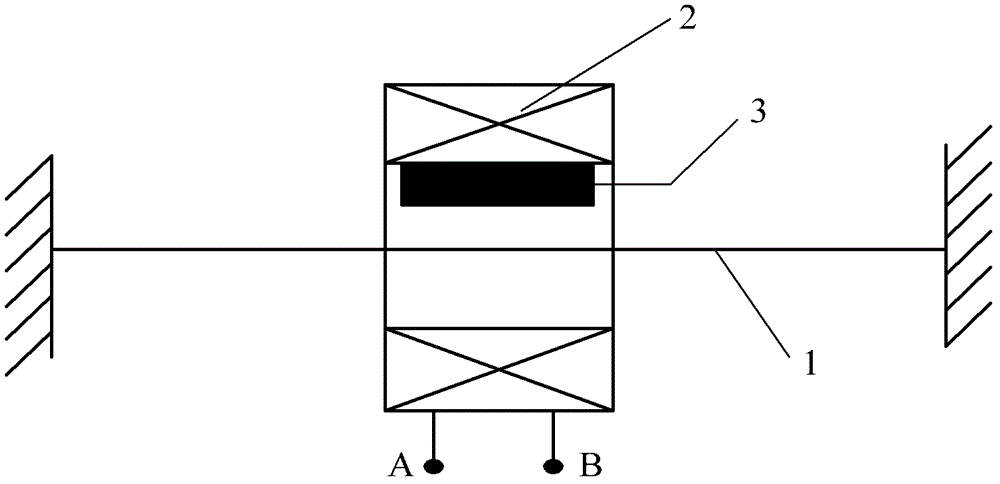
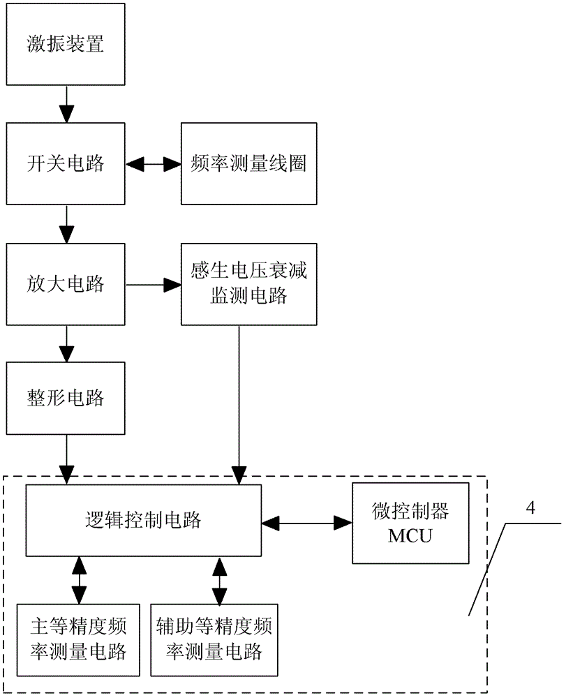
[0033] figure 2 It is a schematic diagram of the preferred structure of the equal-precision frequency measuring device of the single-coil vibrating wire instrument of the present invention. The device includes an excitation device, a switch circuit, an amplifying circuit, a shaping circuit, an induced voltage attenuation monitoring circuit, and an equal-precision frequency measurement circuit 4, wherein the excitation device includes a signal generator, and the switch circuit divides the signal generator and amplifying The circuits are respectively connected with the frequency measuring coils in the single-coil vibrating wire instrument. The time division is specifically that the switch circuit is used as a line selection switch circuit for exciting and picking up vibration. When the switch circuit is first connected to the signal generator and the frequency measurement coil...


PUM


Abstract

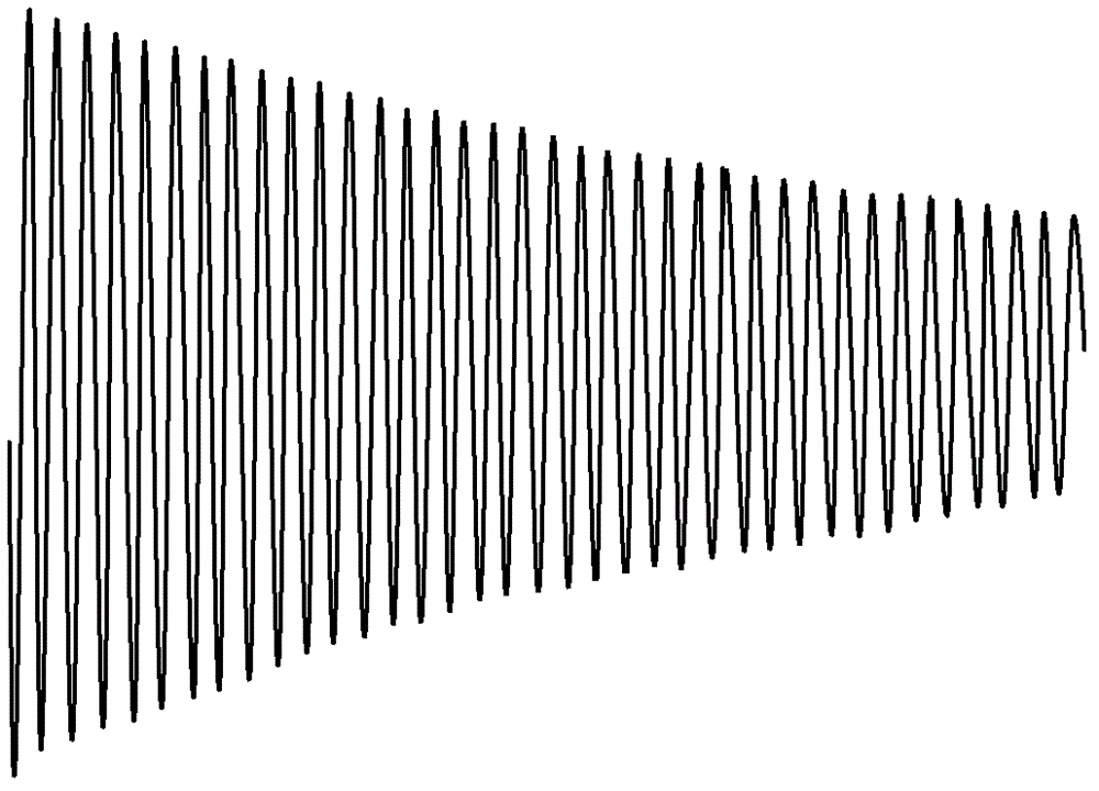
The invention relates to a method and device for measuring the equal precision frequency of a single coil vibrating wire instrument. The method comprises the following steps of: generating induced voltage signals having frequencies accordant with the natural frequency of a string wire and attenuated amplitudes at the two ends of the frequency measuring coil; monitoring the amplitude attenuating conditions of the induced voltage signals through an induced voltage attenuating monitoring circuit; when the monitored amplitude attenuating speeds of the induced voltage signals are up to a preset value, providing a triggering signal for an equal precision frequency measuring circuit; adjusting the measuring time of the equal precision frequency measuring circuit by adjusting a standard referencepulse frequency through the precision frequency measuring circuit; and calculating the frequency of the string wire by using the equal precision frequency measuring circuit according to the induced voltage pulse sample number obtained by counting and the count value of a set standard reference pulse frequency counter. In the method, the lasting time of the measuring process can be adjusted adaptively according to the monitored amplitude attenuating conditions of the induced voltage signals activated by the string wire, so that the equal precision frequency measuring reliability of the single coil vibrating wire instrument is improved.

Description

technical field [0001] The invention relates to the technical field of geotechnical engineering health monitoring, in particular to an equal-precision frequency measurement method and device for a single-coil vibrating wire instrument in a geotechnical engineering safety monitoring instrument. Background technique [0002] In the safety monitoring of geotechnical engineering, safety monitoring instruments such as vibrating wire (or steel string) instruments are usually used to monitor physical quantities such as stress and strain, temperature, joint opening, leakage and deformation of geotechnical engineering. To analyze and judge the safety of geotechnical engineering. [0003] Vibrating wire instruments (or vibrating wire transducers) consist of a homogeneous steel string fixed at both ends. The length of the steel string is L. When sensing the external force F (which can be the stress and strain of geotechnical engineering, temperature, joint opening, leakage and deforma...

Claims


Application Information

Patent Timeline
Patent Type & Authority Patents(China)
IPC IPC(8): G01H11/06
Inventor 江修沈省三毛良明
Owner CHINA GEOKON INSTR
Learn More