Touch panel, driving method for the touch panel, program for getting touch information, and memory media
A technology for a touch display device and a display device, applied to static indicators, data processing input/output processes, instruments, etc., capable of solving problems such as decreased sensitivity of touch information detection, prone to coupling noise, etc.
- Summary
- Abstract
- Description
- Claims
- Application Information
AI Technical Summary
Problems solved by technology
Method used
Image

Examples
Embodiment 1
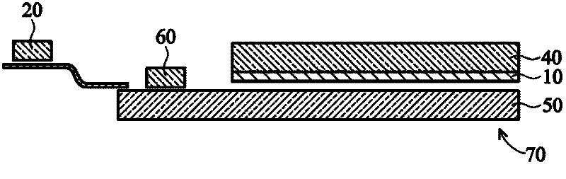
[0050] figure 1 It is a cross-sectional structure diagram of an example of the touch display device 70 according to Embodiment 1 of the present invention. figure 1 Among them, the touch display device 70 of the first embodiment includes a touch sensor 10 , a touch sensor controller 20 , a color filter substrate 40 , a thin film transistor array substrate 50 , and a display device driving circuit 60 .
[0051] The touch sensor 10 and the touch sensor controller 20 constitute a touch sensor module, and the color filter substrate 40 , the thin film transistor array substrate 50 , and the display device driving circuit 60 constitute a display device. The touch sensor 10 is formed on the color filter substrate 40, and the color filter substrate 40 is assembled with the thin film transistor array substrate 50, the display device driving circuit 60 and the touch sensor controller 20 to form a An embedded touch display device 70 . The touch sensor 10 is composed of a transparent ele...
Embodiment 2
[0101] Figure 9 The touch sensor and the driving method of the touch sensor according to the second embodiment of the present invention are described. Figure 9 The same as that of Example 1 is shown in Figure 6 Timing flowcharts in the same format. Wherein, the same constituent elements in Embodiment 2 as those in Embodiment 1 will be marked with the same reference symbols, and descriptions will be omitted.
[0102] Figure 9 Among them, the frame period and driving timing of the display device are the same as Figure 6 same. In the second embodiment, the scan start timing of the touch sensor 10 is started synchronously with the frame period of the display device, which is the same as the first embodiment. In the second embodiment, the reading of touch information from the touch sensor 10 is performed twice in one frame period, which is different from the first embodiment. The reading cycle of the touch sensor 10 is generally shorter than 16.6 msec, and the reading sp...
Embodiment 3
[0108] Figure 10 It describes the touch sensor 10 and the driving method of the touch sensor 10 according to the third embodiment of the present invention. Figure 10 is shown in Example 1 with the Figure 6 with Example 2 Figure 9 Timing flowcharts in the same format.
[0109] In Example 2, reading is performed twice in one frame period, but Example 3 is different from Example 2 in that reading is performed three times in one frame period. At this time, the reading speed of the reading device 22 is set to be higher than 180 Hz. In this way, if Figure 10 As shown, three detected data can be obtained in one frame period.
[0110] The point that the noise cancellation calculation performed by the touch information calculation device 25 is performed in consecutive frame periods is the same as before, and as in the description of the second embodiment, for each of the three detected data, each The moving average between the detection data read out in the same detection se...
PUM
 Abstract
Description
Claims
Application Information
 - R&D
- Intellectual Property
- Life Sciences
- Materials
- Tech Scout
- Unparalleled Data Quality
- Higher Quality Content
- 60% Fewer Hallucinations
Browse by: Latest US Patents, China's latest patents, Technical Efficacy Thesaurus, Application Domain, Technology Topic, Popular Technical Reports.
© 2025 PatSnap. All rights reserved.Legal|Privacy policy|Modern Slavery Act Transparency Statement|Sitemap|About US| Contact US: help@patsnap.com