Virtual electronic whiteboard device

An electronic whiteboard and whiteboard technology, applied in the direction of electrical digital data processing, instruments, data processing input/output process, etc., can solve the problem of inconvenient installation and debugging of the camera, and achieve the effect of convenient installation and debugging

Active Publication Date: 2012-03-14
SHANGHAI EASI COMP TECH
View PDF6 Cites 15 Cited by
  • Summary
  • Abstract
  • Description
  • Claims
  • Application Information

AI Technical Summary

Problems solved by technology

[0009] However, the virtual electronic whiteboard or camera in the prior art is inconvenient to install and debug, or requires multiple line light sources to realize

Method used


Image

  • Virtual electronic whiteboard device
  • Virtual electronic whiteboard device
  • Virtual electronic whiteboard device

Examples


no. 1 example

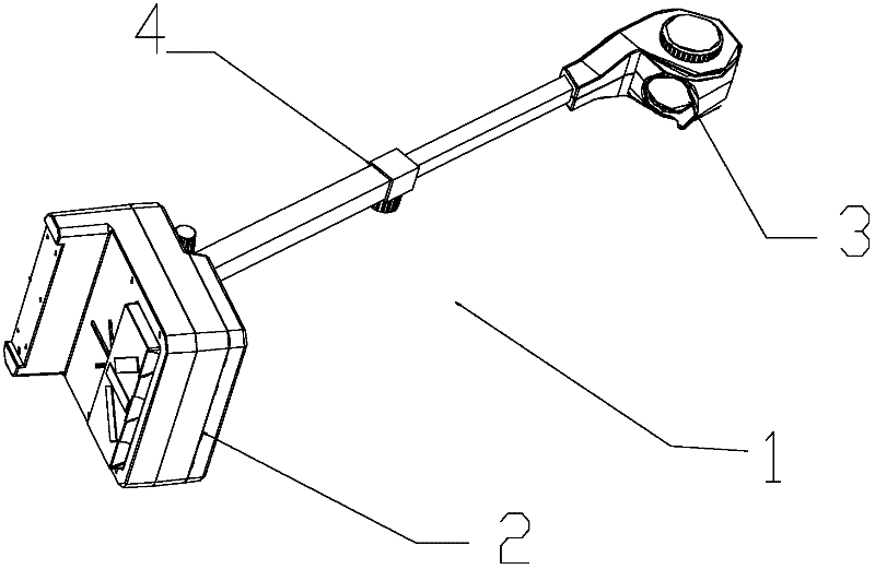
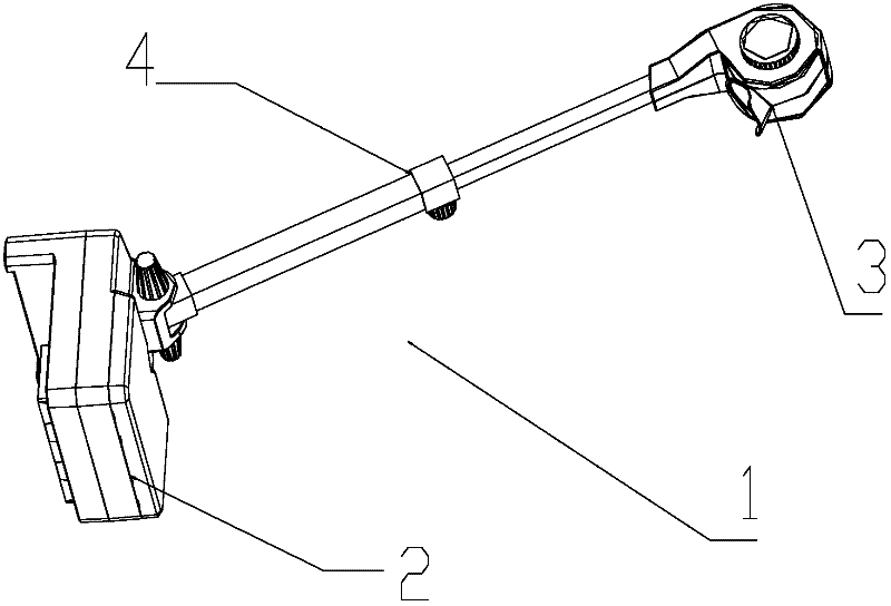
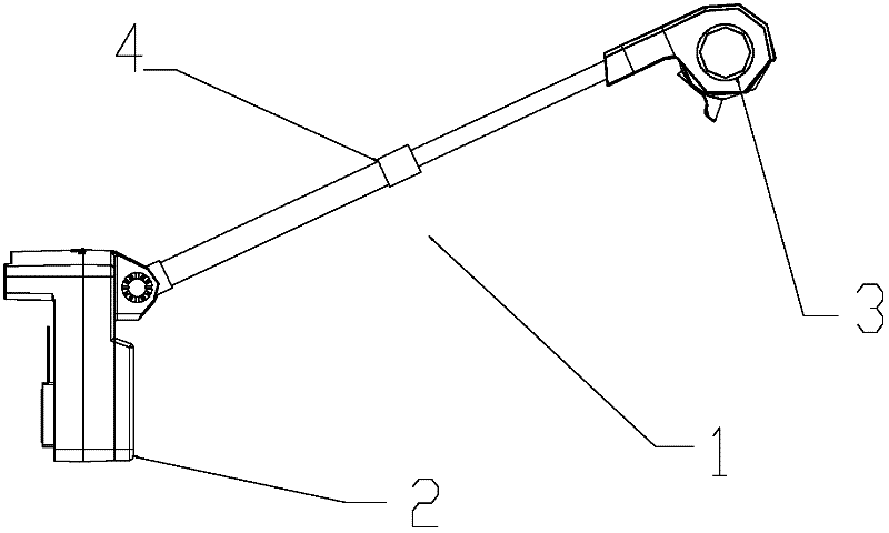
[0088] combine Figure 1 to Figure 6 , the virtual electronic whiteboard device of the present invention includes a line light source 2, a camera 3 and a support rod 4, one end of the support rod 4 is connected to the line light source 2, and the other end is connected to the camera 3,

[0089] The first line light source 2 includes at least one light source body 202 and an optical filter 201, the light source body 202 is installed on the backing plate 203 supported by the bottom plate 206, the bottom plate 206 is fixed in the frame 204 by four bolts 205, the The frame 204 is in close contact with the bracket 207, the bracket 208 and the cover plate 209. The bracket 208 is provided with a knob 210 for adjusting the angle of the support rod 4. The bracket 208 also includes a data board 211, which is connected to the light source body 202 through the wiring harness 212. Connected, the support rod 4 is a telescopic structure, and the camera 3 has an angle-adjustable structure.

...

no. 2 example

[0094] combine Figure 9 to Figure 18 9. A virtual electronic whiteboard device, comprising a second line light source 32, a camera 3 and a support rod 4, one end of the support rod 4 is connected to the second line light source 32, and the other end is connected to the camera 3,

[0095] The second line light source 32 includes at least one light source body 202 and a filter 201,

[0096] It also includes a second whiteboard 8 , the upper area of ​​the second whiteboard 8 has a whiteboard groove surface 82 , and the groove surface 82 has a concave groove surface step 81 for installing the second line light source 32 .

[0097] At least two light source bodies 202 are installed symmetrically inside the rear cover plate 320 of the second line light source 32 , and a cooling fin 324 is closely attached thereto.

[0098] The rear cover 320 of the second line light source 32 has a first installation surface 322 and a second installation surface 323, and there is a raised step 321...


PUM


Abstract

The invention discloses a virtual electronic whiteboard device, which is used for realizing the function of a touch screen on a display plane. The virtual electronic whiteboard device comprises a linear light source and an image information processing device, wherein the linear light source is provided with a camera; the linear light source is arranged on the display plane, so that a light touch surface formed by light rays emitted by the linear light source is parallel to and infinitely close to but is not contacted with the display plane; a visual angle is formed by the camera relative to the display plane, so that an image of the display plane obtained by using the camera is processed by the image information processing device; when a light touch point is formed since the light rays of the light touch surface are blocked by a barrier, the image information processing device is used for judging and recording the position and state of the light touch point in real time through the image obtained by using the camera; and the linear light source at least comprises a light source body. According to the virtual electronic whiteboard device, the linear light source is integrated with the camera, a linear light surface is realized by using one linear light source, and convenience is brought to installation and debugging.

Description

technical field [0001] The invention belongs to the technical field of touch display, in particular to a virtual electronic whiteboard device. Background technique [0002] Existing virtual electronic whiteboards are generally realized by cameras and infrared pens, such as the technical solution disclosed in Chinese patent application No. 200810024947.0. The content of the invention in this application is: "In the present invention, by adopting a device and method for generating touch-sensitive light spots on a plane, the electronic whiteboard of photoelectric technology can truly become a touch screen, and at the same time, plasma, liquid crystal, rear projection, etc. The display is transformed into a touch screen through photoelectric technology. [0003] The object of the present invention is achieved in this way: the device and method for generating touch-sensitive spots on a plane, including at least one linear laser generating device, is characterized in that one or ...

Claims


Application Information

Patent Timeline
Patent Type & Authority Applications(China)
IPC IPC(8): G06F3/042
CPCG06F3/0428
Inventor 戴欢丰徐克
Owner SHANGHAI EASI COMP TECH
Why Eureka
Try Eureka