Dynamic reactive compensation and active filtration system and control method thereof

A dynamic and compensating device technology, applied in active power filtering, reactive power adjustment/elimination/compensation, AC network to reduce harmonics/ripples, etc., can solve problems such as energy waste, poor intelligence, and poor compensation accuracy , to achieve the effect of cost reduction, low cost and good dynamic performance

Inactive Publication Date: 2012-03-14
周玉姝
View PDF3 Cites 3 Cited by
  • Summary
  • Abstract
  • Description
  • Claims
  • Application Information

AI Technical Summary

Problems solved by technology

The reactive power and harmonic pollution of the power grid will cause a large loss of equipment and lines in the power grid, resulting in energy waste, and will also have a great impact on the safe and stable operation of the power system.
[0003] At present, most reactive power compensation devices in power transformation and distribution systems use capacitor banks and reactor components to switch reactive power compensation in groups. This method has the disadvantages of slow compensation speed, large impact, poor compensation accuracy, serious under-compensation and over-compensation. , stepped compensation, poor intelligence and other shortcomings
Although dynamic var compensation devices such as static var compensators can overcome the above shortcomings, due to the limitations of the cost and technical maturity of power electronic devices, a single static var compensator with a large capacity has a lot of problems in design, cost and power consumption. and other aspects can not fully meet the actual needs of the application site
Moreover, the harmonics and reactive power of the power grid often exist together and need to be treated at the same time, but the content of harmonics and reactive power is constantly changing. The traditional method is to configure the management capacity of harmonics and reactive power according to the maximum value according to the line load. , this method causes waste of capacity and increases project cost

Method used


Image

  • Dynamic reactive compensation and active filtration system and control method thereof
  • Dynamic reactive compensation and active filtration system and control method thereof
  • Dynamic reactive compensation and active filtration system and control method thereof

Examples


Embodiment Construction

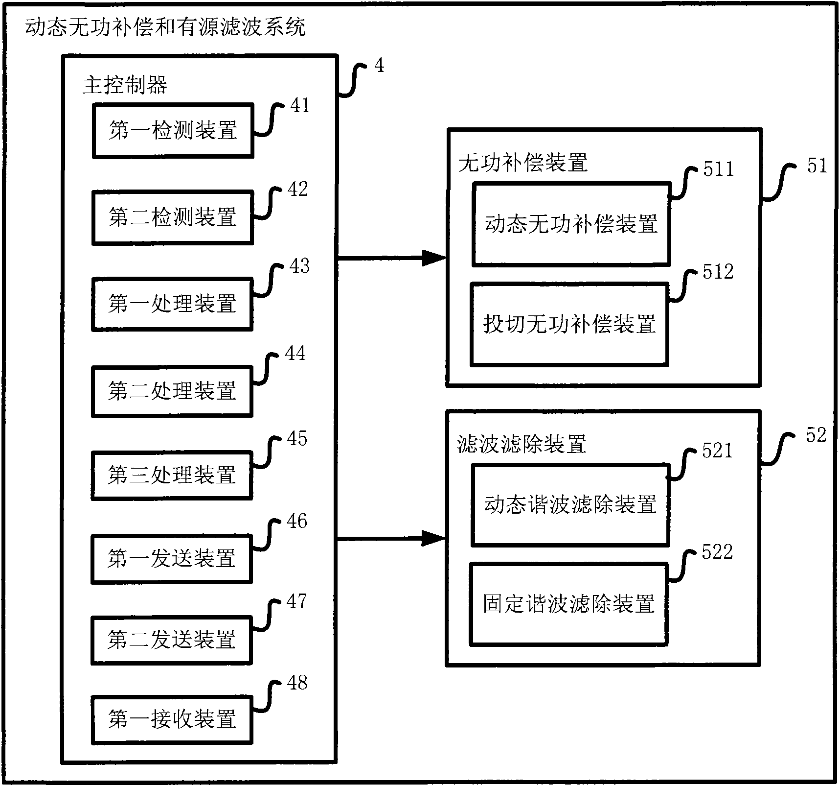
[0034] figure 1 The structure of the dynamic reactive power compensation and active filter system according to the first embodiment of the present invention is shown. Specifically, in this embodiment, the dynamic reactive power compensation and active filter system includes a main controller 4, a reactive power compensation device 51, and a harmonic filtering device 52. More specifically, the main controller 4 includes a first detection device 41, a second detection device 42, a first processing device 43, a second processing device 44, a third processing device 45, a first sending device 46, a second The transmitting device 47 and the first receiving device 48; the reactive power compensation device 51 preferably includes a dynamic reactive power compensation device 511 and a switching reactive power compensation device 512; the harmonic filtering device 52 preferably includes dynamic harmonic filtering Eliminating device 521 and fixed harmonic filtering device 522. Wherein,...


PUM


Abstract

The invention provides a dynamic reactive compensation and active filtration system, which comprises a main controller, a dynamic reactive compensation device, a switching reactive compensation device, a dynamic harmonic wave filtering device and a fixed harmonic wave filtering device. The invention also provides a corresponding control method. In the invention, various parallel compensation units are combined, an efficient and reasonable switching strategy is used for coordinating the work of each unit so as to meet the actual needs to the maximum extent. The system disclosed by the invention has the functions of quick, smooth and large-capacity reactive compensation and harmonic wave filtration, simultaneously the capacity configuration is reasonable and flexible, the device cost is low, the protection reliability is high, the operation is intelligent, and optimum combination of the effect, the intelligence, the cost and the stability is realized, so the invention can be widely applied in the fields of reactive compensation and harmonic wave filtration of a power grid.

Description

Technical field [0001] The invention relates to a reactive power compensation system, in particular to a dynamic reactive power compensation and active filter system and a control method thereof. Background technique [0002] Electricity is an important material guarantee for social and economic development. In recent years, power users have increasingly higher requirements for power quality, and the application of a large number of non-linear loads on the user side has also become an important factor in the deterioration of power quality of the power grid, from small-capacity household appliances to large Industrial AC / DC converters with high capacity will cause distortion of grid current and voltage waveforms and drop in power factor. It can be said that user load is becoming the main source of grid reactive power and harmonic pollution problems. Reactive power and harmonic pollution of the power grid will cause a lot of equipment and line losses in the power grid, resulting in...

Claims


Application Information

Patent Timeline
Patent Type & Authority Applications(China)
IPC IPC(8): H02J3/18H02J3/01
CPCY02E40/20
Inventor 周玉姝
Owner 周玉姝
Why Eureka
Try Eureka