Manufacturing method of washer

A manufacturing method and technology of Wasser, applied in the direction of engine components, mechanical equipment, etc., can solve problems such as interruption of high-speed mass production, shortened service life of molds and fixtures, and large material deformation, so as to prolong service life and improve mechanical properties , the effect of slowing down the speed

Inactive Publication Date: 2012-03-21
春日机械工业股份有限公司
View PDF5 Cites 6 Cited by
  • Summary
  • Abstract
  • Description
  • Claims
  • Application Information

AI Technical Summary

Problems solved by technology

[0008] Although the above washer manufacturing method can forge the wire 22 into the washer finished product 23 by cold forging, from the above steps (a) to (b), the round bar-shaped working section will be formed after only one forging. 222 is forged into an oblate prototype 223, and the deformation of the material is relatively large, which will lead to poor mechanical properties of the finished washer product 23.
And because it is stamping and cold forging directly on the wire rod 22, the working section 222 is connected with the pinch section 221 at the rear, and the clamp 212 and the feeding seat 211 are clamped in the pinch section 221, so in the stamping process, the clamp 212 and the feeding seat 211 will bear the impact force of the punch 214 and the relative friction from the pinch section 221, causing the fixture 212 and the feeding seat 211 to wear and tear and be damaged
And in the re-forging step (c), the punch rod 214 needs to push the pinch section 221 connected to the rear while punching and piercing, so that the washer finished product 23 is separated from the pinch section 221. The punching required for this step The forging force is quite large, and it will also shorten the service life of the mold and fixture, which will not only affect the accuracy of clamping and feeding, increase the defect rate, and cause cost losses that are difficult to ignore. When the forging equipment 21 is shut down for repairs, it will also The high-speed mass production operation is interrupted, resulting in reduced output and poor production efficiency

Method used


Image

  • Manufacturing method of washer
  • Manufacturing method of washer
  • Manufacturing method of washer

Examples


Embodiment Construction

[0031] The present invention will be described in detail below in conjunction with the accompanying drawings and embodiments.

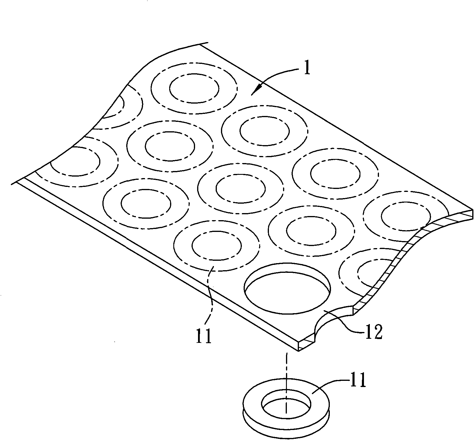
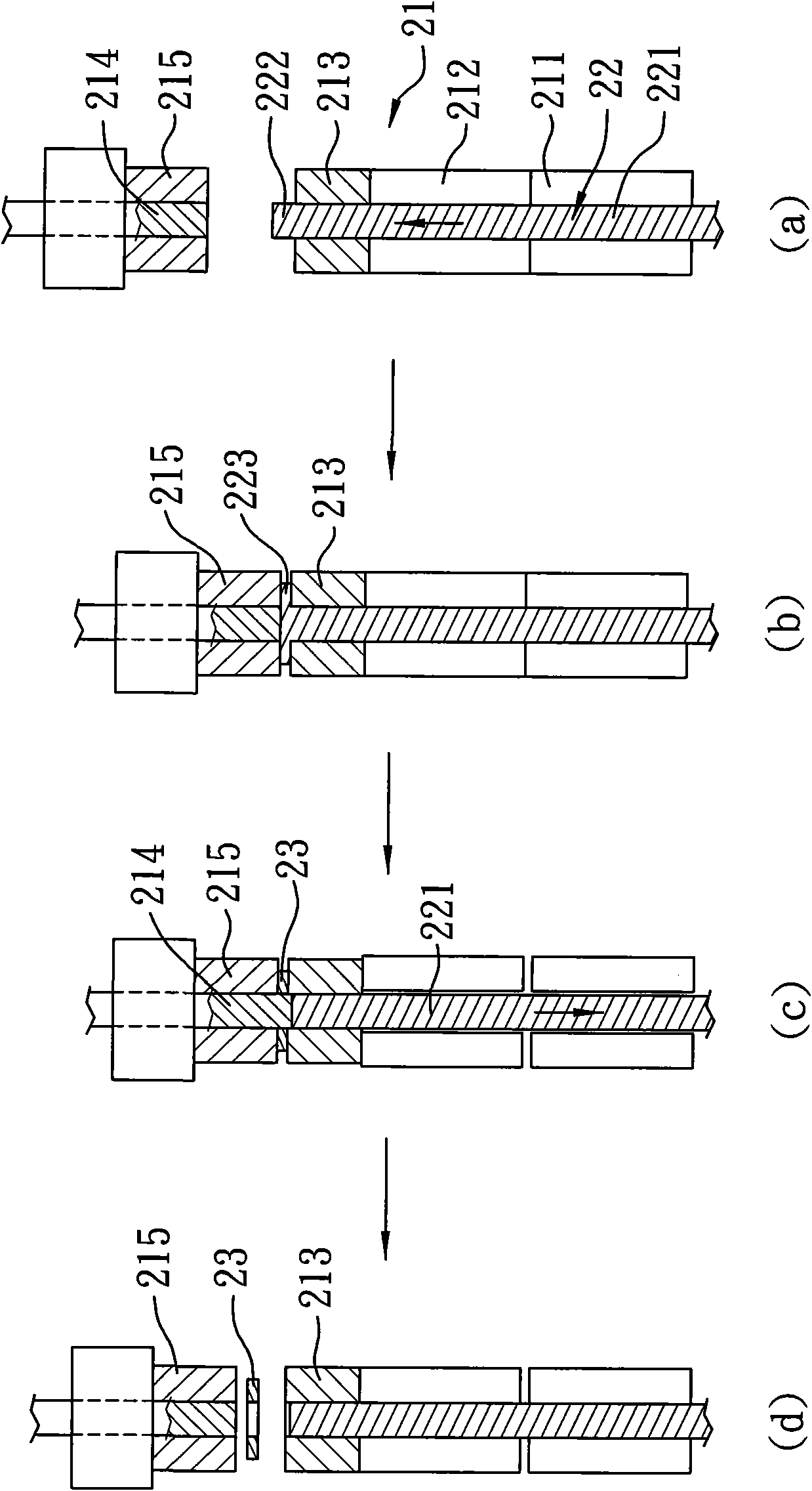
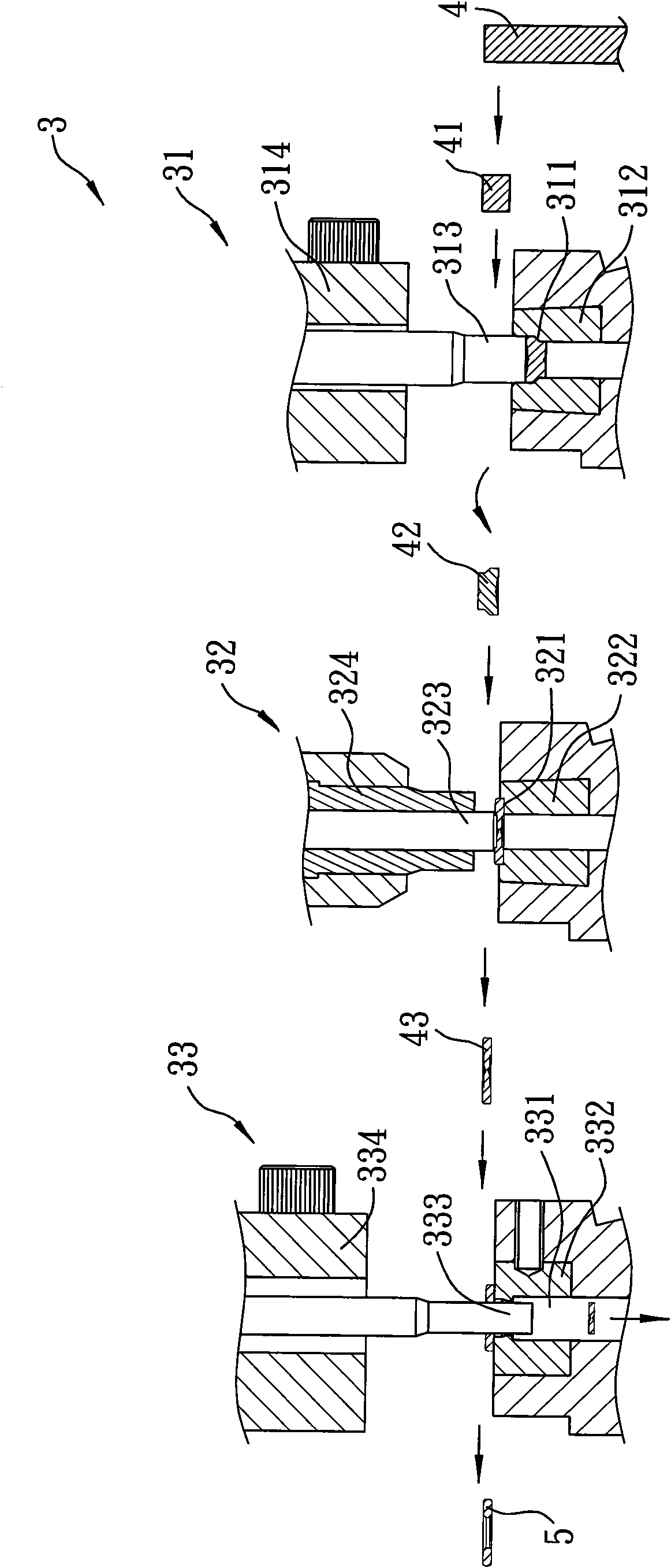
[0032] refer to image 3, the first preferred embodiment of the washer manufacturing method of the present invention is to use a forging equipment 3 to forge a wire 4 into a washer finished product 5. The forging equipment 3 includes a first forging device 31 and a second forging device 32, and a third punching device 33. The first punching device 31 includes a first female die 312 with a first die cavity 311, and a first male die 314 with a first punch 313 that can be driven to move toward the first female die 312 . The second punching device 32 includes a second female die 322 with a second die cavity 321, and a second male die 324 that has a second punch 323 and can be driven to move toward the second female die 322. . The third forging device 33 includes a third female die 332 having a through hole 331 , and a third male die 334 having a third...


PUM


Abstract

The invention relates to a manufacturing method of a washer. The manufacturing method utilizes forging equipment to forge a wire into a washer finished product and comprises the following steps of: a step of cutting out a blank, a step of initially forging a rough blank, a step of reforging a prototype and a step of punching and forming. In the step of cutting out the blank, the wire is cut out by a section of length so as to form a blank. In the step of initially forging the rough blank, the forging equipment is utilized for forging the blank initially so as to form the rough blank. In the step of reforging the prototype, the forging equipment is utilized for punching and forging the rough blank so as to form a flat prototype product with the shape of the washer. In the step of punching and forming, the forging equipment is utilized for punching and penetrating a central part of the prototype product so as to form a finished washer product with a penetrated hole. In the manufacturing method, after the step of cutting out the blank, the step of initially forging the rough blank is carried out, and then the step of reforging the prototype is carried out, so that the blank is changed into the prototype product from the rough blank, further the mechanical property of the finished product can be really improved, the loss of a punching and forging device can be reduced and the service life can be prolonged.

Description

technical field [0001] The invention relates to a washer manufacturing method for forming washer. Background technique [0002] refer to figure 1 , a conventional washer manufacturing method, using a punch (not shown) to punch out several washer finished products 11 on a metal plate 1, the manufacturing steps are to prepare a metal plate 1 with a predetermined thickness first, and then The metal plate 1 is sent into a punching machine to directly punch out a hollow ring-shaped washer finished product 11 on the metal plate 1 . However, after the metal plate 1 passes through the blank blanking process, the remaining material 12 located around the washer finished product 11 will be left, forming a large amount of waste and causing waste, and the mechanical strength of the washer finished product 11 produced by it is not good. The cutting surface around the edge is even sharper, and the texture of the product is low, so its manufacturing method still needs to be improved. [...

Claims


Application Information

Patent Timeline
Patent Type & Authority Applications(China)
IPC IPC(8): B21K1/76
Inventor 李锡昌
Owner 春日机械工业股份有限公司
Why Eureka
Try Eureka