
Production method of corrugated gas collecting pipeline member for air-conditioner

A production method and gas collecting pipe technology are applied in the production field of corrugated gas collecting pipe fittings for air conditioners, and can solve problems such as dead bending, difficult assembly, and impact on air conditioner performance.

Active Publication Date: 2012-03-21
GOLDEN DRAGON PRECISE COPPER TUBE GROUP +1
View PDF6 Cites 2 Cited by
  • Summary
  • Abstract
  • Description
  • Claims
  • Application Information

AI Technical Summary

Problems solved by technology

This kind of products used to be directly drawn from the copper tube, and then bent. Because the pipeline itself is long and the diameter of the copper tube is large, the copper tube with a large diameter is very hard and very hard when the air conditioner is assembled and the whole machine is installed later. Difficult to assemble. At the same time, copper pipes are prone to wrinkling and dead bends. At present, the existing pipeline parts have a single processing form and a variety of process combinations. Multiple solder joints and external parts are required, which not only increases the cost but also buryes hidden dangers. , has a great influence on the performance of the air conditioner

Method used


Image

  • Production method of corrugated gas collecting pipeline member for air-conditioner
  • Production method of corrugated gas collecting pipeline member for air-conditioner
  • Production method of corrugated gas collecting pipeline member for air-conditioner

Examples


Embodiment 1

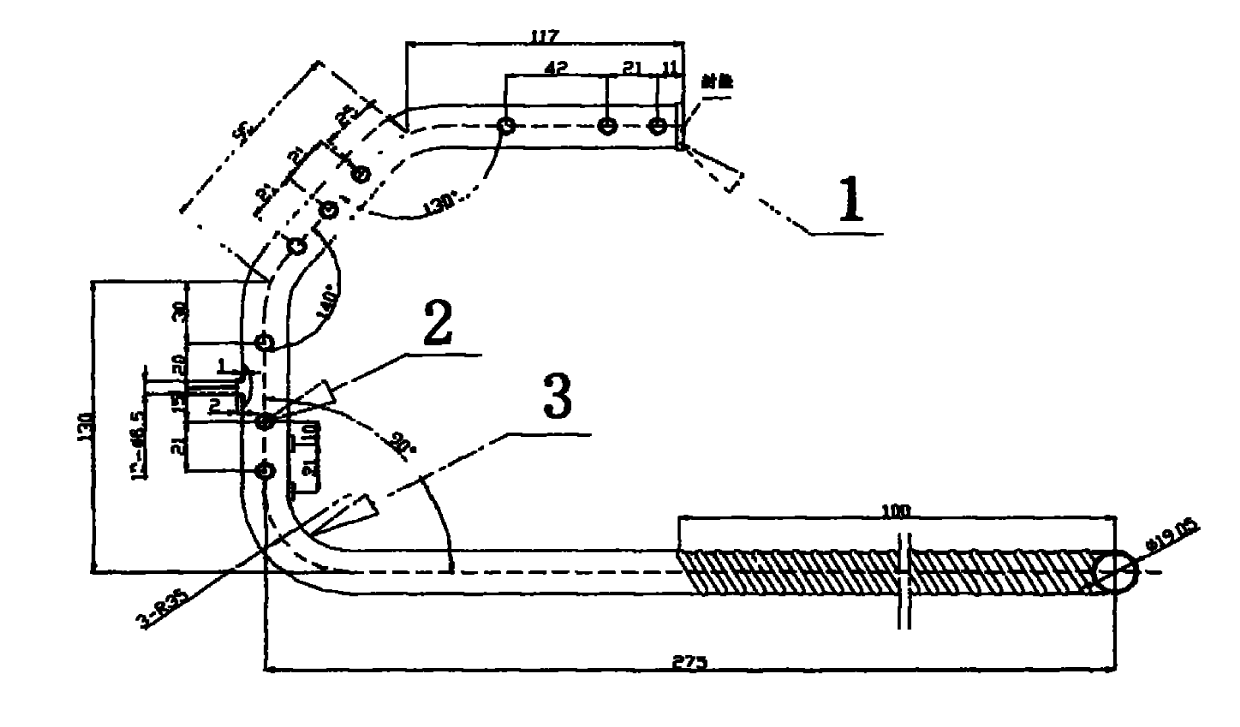
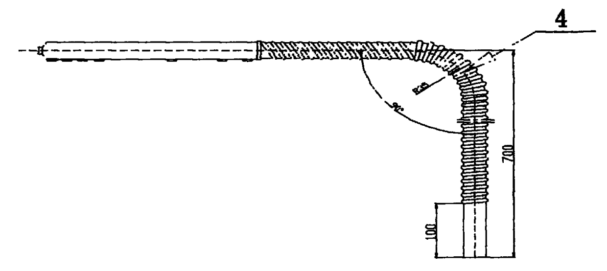
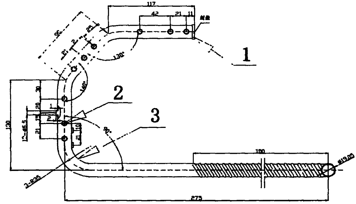
[0017] Embodiment 1: Under the premise of the prior art, the copper tube is first processed into a corrugated tube, such as figure 1 As shown in the figure, the corrugated wheel and other auxiliary equipment are combined, and the processing length is automatically controlled by the travel switch, and finally qualified corrugated pipe products can be produced. The positioning point is used to pull out the table. The table is pulled out by positioning a hole with a diameter of φ3.2, turning a hole with an inner diameter of φ6.5 and a table height of 2.5mm, and then adjusting the hole to a hole with an inner diameter of φ6.5 and a table height of 2mm. Repeat the bending of 140 degrees again to locate the puller, and the third time to bend 130 degrees to locate the puller. Then anneal the product, and focus on the bending of the thread to ensure the bending range and number of bending, and the other parts are treated lightly. Bending bellows with special molds to meet the bending...

Embodiment 2

[0018] Example 2: First, the copper pipe is processed into a corrugated pipe, which is combined with corrugated wheels and other auxiliary equipment, and the processing length is automatically controlled by the travel switch. Finally, qualified corrugated pipe products can be produced, and then the dial table is determined and the pull table is pulled out. The position of the machine is determined, then it is bent through a special mold, and the table is pulled out at the positioning point. The table is pulled out by positioning a hole of φ4.0, turning a hole with an inner diameter of φ7.0, and a table height of 3mm, and then calibrating the hole as A hole with an inner diameter of φ7.0 and a table height of 2.5mm. Repeat the bending of 150 degrees again to locate the pull-out table, and the third bend of 140 degrees to locate the pull-out table. Then anneal the product, and focus on the bending of the thread to ensure the bending range and number of bending, and the other par...


PUM


Abstract

The invention provides a novel corrugated gas collecting pipeline member, wherein a section of copper pipe is machined into a corrugated pipe, and the copper pipe can be freely bent back and forth during air-conditioner assembly and complete set installation, and therefore the problems of corrugation and dead turn during installation are solved. Meanwhile, a drawing station, a sealing cap, bending, the corrugated pipe, welding and the like are combined together through accurate calculation, smart design and exquisite technologies, therefore the practicability of the product is increased; in addition, no new equipment is increased under the conventional production conditions, therefore product diversification and high return with small investment are realized.

Description

technical field [0001] The invention belongs to a production method of a corrugated gas collecting pipe fitting for air conditioning. Background technique [0002] The main function of the gas collecting pipe in the air conditioner is to collect all the gas in the evaporator to the gas collecting pipe, and connect it to the external unit through the gas collecting pipe, so as to play a role in a cycle. This kind of product used to be directly pulled out of the copper tube and then bent. Because the pipeline itself is long and the diameter of the copper tube is large, when the air conditioner is assembled and the whole machine is installed in the later stage, the diameter of the copper tube is large and the tube body is very hard and very hard. It is difficult to assemble, and at the same time, copper pipes are prone to wrinkling and dead bending. At present, the existing pipeline parts have a single processing form, a variety of process combinations, and the need for multipl...

Claims


Application Information

Patent Timeline
Patent Type & Authority Applications(China)
IPC IPC(8): B23P15/00
Inventor 周强曹相杰赵成刚刘涛蔡春超吴雪娇
Owner GOLDEN DRAGON PRECISE COPPER TUBE GROUP
Learn More