Ram deflection deformation compensation device

A deformation compensation device and ram technology, applied in other manufacturing equipment/tools, large fixed members, metal processing machinery parts, etc., can solve problems such as deflection and deformation of ram components, ensure machining accuracy, improve machine tool accuracy, save money human effect

Inactive Publication Date: 2012-03-21
WUHU HENGSHENG HEAVY MACHINE TOOL
View PDF7 Cites 7 Cited by
  • Summary
  • Abstract
  • Description
  • Claims
  • Application Information

AI Technical Summary

Problems solved by technology

[0011] The invention provides a ram deflection and deformation compensating device, the purpose of which is to

Method used


Image

  • Ram deflection deformation compensation device
  • Ram deflection deformation compensation device
  • Ram deflection deformation compensation device

Examples


Embodiment Construction

[0026] The specific implementation of the present invention will be described in further detail below by describing the embodiments with reference to the accompanying drawings, so as to help those skilled in the art have a more complete, accurate and in-depth understanding of the inventive concepts and technical solutions of the present invention.

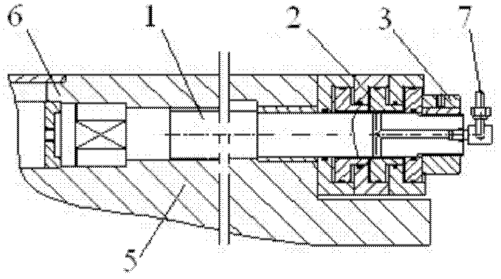
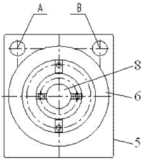
[0027] Such as figure 1 The structure of the present invention expressed, the present invention is a ram deflection deformation compensation device, which is applied to the ram 5 on the headstock of a heavy machine tool.

[0028] In the main shaft hole at the center of the ram 5, there is a boring shaft 8 slidingly fitted in the hole.

[0029] In order to solve the problems existing in the current known technology described in the background technology section of this specification and overcome its defects, and realize the purpose of the invention to solve the problem of deflection and bending deformation of the ram parts when the ...


PUM


Abstract

The invention discloses a ram deflection deformation compensation device. A pull rod is arranged at the upper part of a ram along the axis direction of the ram and in a pull rod hole on the ram; a counter bore at the front end of the ram is matched with an end part circular bead at the front part of the pull rod; and at the rear part of the ram, the pull rod is fastened by a force transmission nut. Due to adoption of the technical scheme, the pulling force of the pull rod is adjusted continuously; straightness of the ram at each position in the moving and extending process is not changed; rigidity when the ram and a main shaft system move is improved; the rotary precision of the main shaft is effectively improved; and the processing precision of parts when a machine tool is used for cutting is guaranteed. Fit clearance is eliminated; predeformation occurs between the contact surfaces of the rams; the production efficiency is improved; manpower and material resources are saved; and innovative features are achieved in the aspects of technique, performance and structure.

Description

technical field [0001] The invention belongs to the technical field of machine tool structures, and relates to the structure technology of the spindle box of large machine tools, especially heavy-duty floor milling and boring machines. More specifically, the invention relates to a compensation device for deflection and deformation of rams. Background technique [0002] Improving the accuracy and stability of machine tools has always been the development direction of machine tool manufacturing technology. [0003] During the processing of heavy-duty machine tools such as CNC heavy-duty floor milling and boring machines, the ram of the machine tool moves forward and backward in the headstock, and the boring shaft can move horizontally in the ram supported by it. They protrude from the headstock The distance is generally relatively large, the maximum moving distance can reach 1.2m respectively, and the overlapping distance of the two can reach 2.4m, and in some CNC heavy-duty f...

Claims


Application Information

Patent Timeline
IPC IPC(8): B23Q23/00B23Q1/25
Inventor 胡子俊潘康健孙跃华
Owner WUHU HENGSHENG HEAVY MACHINE TOOL
Why Eureka
Try Eureka