Electric power line communication system for vehicle
A technology of power line communication and power line, which is applied in the direction of distribution line transmission system, vehicle components, circuits or fluid pipelines, and can solve problems such as complex structures
- Summary
- Abstract
- Description
- Claims
- Application Information
AI Technical Summary
Problems solved by technology
Method used
Image

Examples
no. 1 example
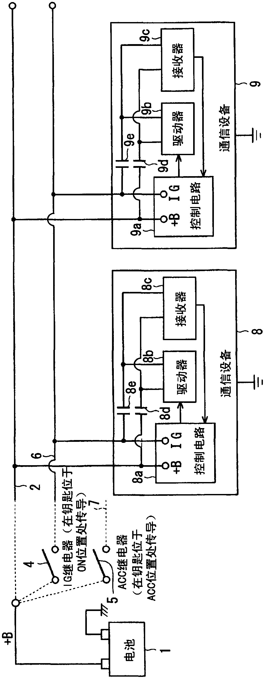
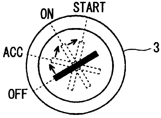
[0015] Figure 1A A power line communication system mounted on a vehicle is shown. A battery 1 as a power source having a positive electrode for supplying a voltage of 12 volts is connected to a +B line 2 as a power line. Further, battery 1 is connected to IG (ie, ignition) line 6 and ACC (auxiliary) line 7 via IG relay 4 and ACC relay 5 . Here, the IG relay 4 and the ACC relay 5 provide a key switch. IG relay 4 and ACC relay 5 according to the Figure 1B The position of the lock cylinder 3 shown in to switch on and off. The negative electrode of the battery 1 is connected to the vehicle body as a ground.
[0016] Communication devices 8 and 9 as in-vehicle devices are connected to the +B line 2 and the IG line 6 . Here, although the system includes two devices, the system may include one or more devices, such as including three communication devices. The +B line 2 and the IG line 6 provide a power line pair as a communication line pair in order to perform power line comm...
no. 2 example
[0028] Figure 4 A power line communication system mounted on a vehicle according to the second embodiment is shown. Figure 4 corresponds to Figure 1A . Communication devices 10 and 11 instead of devices 8 and 9 communicate with each other via +B line 2 and ACC line 7 . Therefore, one of the communication lines is not the IG line 6 but the ACC line 7 . Specifically, when the position of the lock cylinder 3 is at one of the ACC position, the ON position and the START position, the potential of the ACC line 7 is 12 volts. Therefore, when the potential of the ACC line 7 is 12 volts, each control circuit 10a, 11a of the communication devices 10 and 11 determines that the position of the lock cylinder 3 is at one of the ACC position, the ON position and the START position. When the potential of the ACC line 7 is 0 volts, the control circuits 10a, 11a of the communication devices 10, 11 determine that the position of the lock cylinder 3 is at the OFF position. Therefore, effec...
no. 3 example
[0030] Figure 5 and Figure 6 A power line communication system mounted on a vehicle according to the third embodiment is shown. Figure 5 corresponds to Figure 4 . Communication devices 12 and 13 instead of devices 10 and 11 communicate with each other via IG line 6 and ACC line 7 . Therefore, one of the communication lines is not the +B line 2 but the IG line 6 . Therefore, when one of the IGF relay 4 and the ACC relay 5 is turned on, the communication device 12, 13 is powered so that the device 12, 13 starts to operate.
[0031] Figure 6 A flowchart of the process performed by the control circuit 12a of the communication device 12 is shown. When one of the IG relay 4 and the ACC relay 5 is turned on, the device 12 starts to perform Figure 6 in the process. In steps S11 and S12, the control circuit 12a determines whether the voltage of the ACC line 7 and the voltage of the IG line 6 are 12 volts or 0 volts, respectively. When the voltages of both the ACC line 7 ...
PUM
 Abstract
Description
Claims
Application Information
 - R&D
- Intellectual Property
- Life Sciences
- Materials
- Tech Scout
- Unparalleled Data Quality
- Higher Quality Content
- 60% Fewer Hallucinations
Browse by: Latest US Patents, China's latest patents, Technical Efficacy Thesaurus, Application Domain, Technology Topic, Popular Technical Reports.
© 2025 PatSnap. All rights reserved.Legal|Privacy policy|Modern Slavery Act Transparency Statement|Sitemap|About US| Contact US: help@patsnap.com