Automatic lifting device for flue damper of kiln

A technology of flue shutter and electric device, applied in valve device, exhaust gas device, valve operation/release device, etc., can solve the problem that the furnace wall and related accessories are easily burnt out, the heating time is prolonged, and it is difficult to guarantee the furnace Pressure and other problems, to achieve the effect of simple structure, prolong service life and reduce labor intensity

Inactive Publication Date: 2012-03-21
江苏腾达环境工程有限公司
View PDF0 Cites 6 Cited by
  • Summary
  • Abstract
  • Description
  • Claims
  • Application Information

AI Technical Summary

Problems solved by technology

After a long period of use, it is found that the best state is to control the furnace pressure between positive 100Pa and positive 300Pa. If the flue gate is manually controlled, it can only be operated with the experience of the operator, and it is difficult to ensure the furnace pressure.
When the furnace pressure is less than 100Pa, the heating time will be prolonged, and the heat energy will be sucked away by the flue, which wastes a lot of production energy; when the furnace pressure exceeds 300Pa, the furnace wall and related accessories will be easily burned

Method used


Image

  • Automatic lifting device for flue damper of kiln
  • Automatic lifting device for flue damper of kiln

Examples


Embodiment Construction

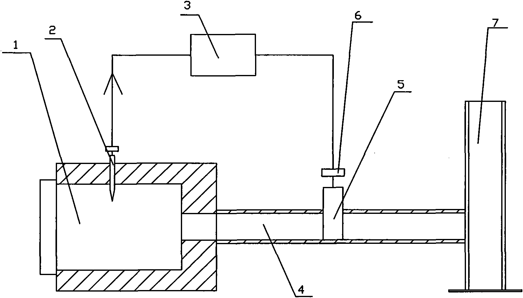
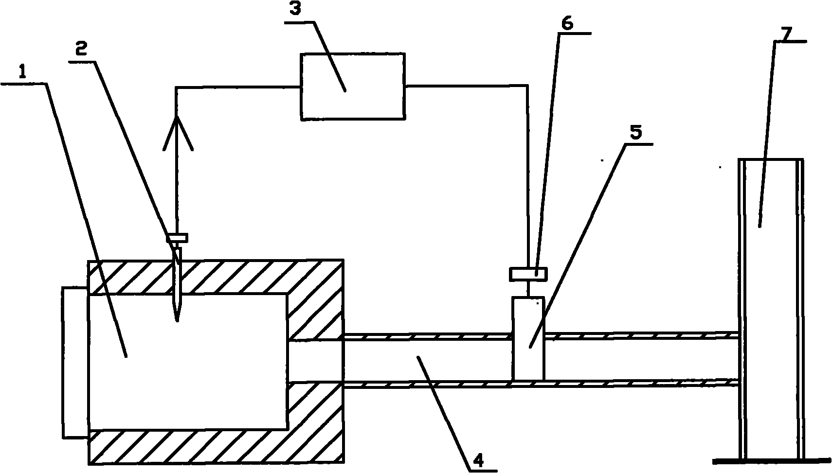
[0008] A kiln flue gate automatic lifting device, the kiln 1 communicates with the chimney 7 through the flue 4, the flue 4 is provided with a gate 5, the device includes a pressure device 2, an electric device 6, the The pressure device 2 is arranged in the hearth of the kiln 1, and the PLC control device 3 is provided between the pressure device 2 and the electric device 6, and the electric device 6 is connected with the gate plate 5. When the pressure in the hearth of kiln 1 is not within the optimum working pressure range, the pressure device 2 sends a signal to the PLC control device 3, and the PLC control device 3 starts the electric device 6 to open the gate 5, thereby controlling the pressure in the furnace to return to the maximum Good working pressure.


PUM


Abstract

The invention relates to an automatic lifting device for a flue damper of a kiln. The kiln is communicated with a chimney through a flue; a damper is arranged in the flue. The automatic lifting device comprises a pressure gauge and an electric device, wherein the pressure gauge is arranged in a hearth of the kiln; a PLC (Programmable Logic Controller) is arranged between the pressure gauge and the electric device; and the electric device is connected with the damper. The automatic lifting device is simple in structure and can automatically lift the flue damper according to the pressure intensity in the hearth of the kiln and ensure that the pressure in the hearth is within the best working scope, thereby improving the work efficiency of the kiln, saving the produced energy resources, also prolonging the service life of the kiln and related equipment and greatly reducing the labor intensity of workers.

Description

technical field [0001] The invention relates to a device for automatically adjusting pressure in a furnace chamber of a kiln, in particular to a device for automatically lifting and lowering a gate plate of a kiln flue. Background technique [0002] At present, the furnace pressure of many furnace chambers is generally not controlled or the pressure in the furnace is adjusted by manually controlling the flue gate, and the pressure in the furnace is an important parameter for the performance of the furnace. After a long period of use, it is found that the best state is to control the furnace pressure between positive 100Pa and positive 300Pa. If the flue gate is manually controlled, it can only be operated with the experience of the operator, and it is difficult to ensure the furnace pressure. When the furnace pressure is less than 100Pa, the heating time will be prolonged, and the heat energy will be sucked away by the flue, which wastes a lot of production energy; when the ...

Claims


Application Information

Patent Timeline
Patent Type & Authority Applications(China)
IPC IPC(8): F23J13/08F16K31/02
Inventor 葛乃逍张乃鹏
Owner 江苏腾达环境工程有限公司
Why Eureka
Try Eureka