Thermopile infrared sensor and manufacture method thereof
What is AI technical title?
AI technical title is built by PatSnap AI team. It summarizes the technical point description of the patent document.
An infrared sensor and thermopile technology, applied in the field of infrared sensors, can solve the problems of reduced yield and incompatible IC technology, and achieve the effect of reducing production costs
Active Publication Date: 2013-04-24
北京中科微投资管理有限责任公司
View PDF1 Cites 0 Cited by
Summary
Abstract
Description
Claims
Application Information
AI Technical Summary
This helps you quickly interpret patents by identifying the three key elements:
Problems solved by technology
Method used
Benefits of technology
Problems solved by technology
[0005] However, the problem is that the production process of absorbing layer materials such as gold black or silver black coating is not compatible with conventional IC processes, and the release process used to form the cavity below and around the cantilever beam is a wet release process , this process will result in lower yield
Method used
Image
Click on the blue label to locate the original text in one second.
Reading with bidirectional positioning of images and text.
Examples
Embodiment 1
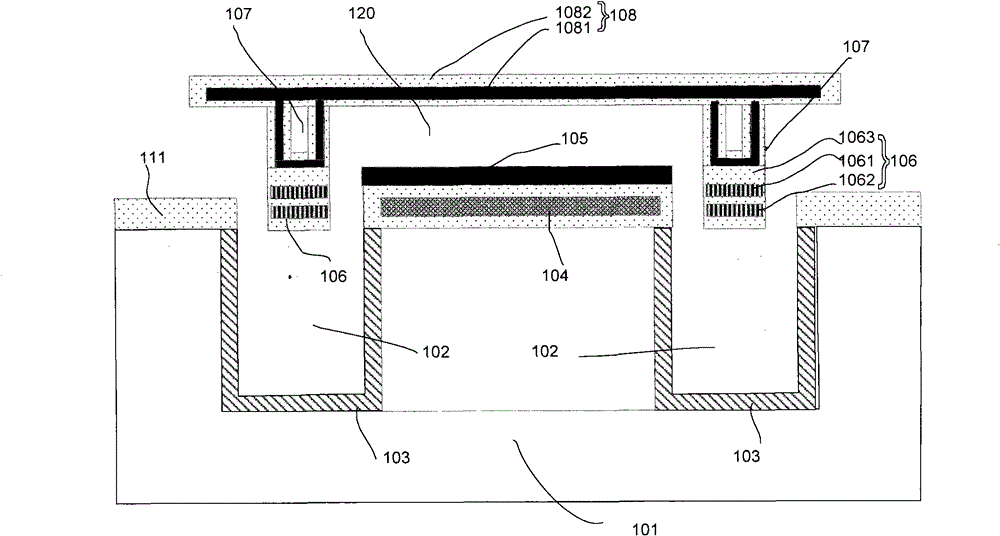
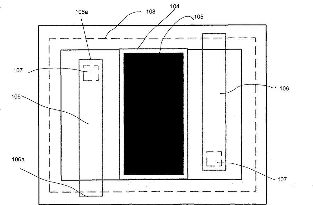
[0057] figure 2 It is a structural sectional view of a thermopile infrared sensor in this embodiment, image 3 for figure 2 In the top view of the structure of the thermopile infrared sensor, in order to clearly show the invention point, only one detection unit is shown in the figure, and the actual thermopile infrared sensor is composed of a plurality of such detection units.
[0058] As shown in the figure, the thermopile infrared sensor includes:
[0059] a substrate 101, the substrate 101 has a groove 102 therein;
[0060]The absorbing layer 108 is located above the substrate 101 and has a certain distance from the surface of the substrate 101;
[0061] The reflective layer 105 is formed on the surface of the substrate outside the trench 102, completely under the absorbing layer 108, and has a cavity 120 between it and the absorbing layer 108;
[0062] The readout circuit layer 104 is located on the substrate surface below the reflective layer 105, and is used to out...
Embodiment 2
[0089] Figure 9 It is a cross-sectional view of the structure of the thermopile infrared sensor in this embodiment. As shown in the figure, the thermopile infrared sensor also includes: a substrate 201 with a groove 202, an absorbing layer 208 located above the substrate 201, a reflective layer 205 located on the surface of the substrate outside the groove, the The cavity 229 between the reflection layer 205 and the absorption layer 208, the cantilever beam 206 composed of thermocouple pairs, and the readout circuit layer 204 under the reflection layer.
[0090] The difference from Embodiment 1 is that: the substrate is an SOI substrate, which includes a bottom silicon layer, a buried oxide layer and a top silicon layer, and the trench 202 is located in the bottom silicon layer; the thermocouple pair is P Type single crystal silicon and N type single crystal silicon, or, the thermocouple pair is metal and single crystal silicon. Thus, both the P-type single crystal silicon ...
PUM
Abstract
The invention provides a thermopile infrared sensor and a manufacture method thereof. The thermopile infrared sensor comprises a substrate, an absorbing layer, a reflecting layer and a cantilever beam, wherein grooves are arranged in the substrate, the absorbing layer is positioned above the substrate, the reflecting layer is positioned on the surface of the substrate arranged outside the grooves, a cavity is arranged between the reflecting layer and the absorbing layer, the cantilever beam consisting of thermocouple pairs is positioned above the grooves, the cold ends of the thermocouple pairs are connected with the substrate, and hot ends of the thermocouple pairs are connected with the absorbing layer arranged above the hot ends through support posts. The inner surfaces of the grooves are provided with release blocking layers. Because the infrared absorption efficiency is improved by adopting a resonance absorption mode, the reflecting layer, the absorbing layer and the medium layer are made through processes and materials used in conventional integrated circuit (IC) processes, the compatibility with the existing IC process can be easily realized, the manufacture cost is reduced, and the large-range popularization and the application are favorably realized.
Description
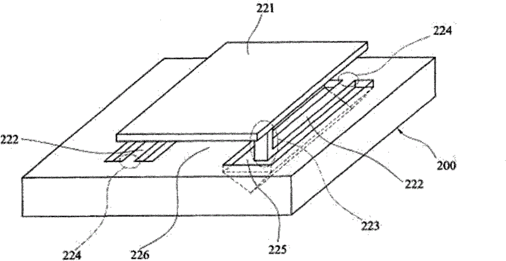
technical field [0001] The invention relates to the technical field of infrared sensors, in particular to a thermopile infrared sensor and a manufacturing method thereof. Background technique [0002] In the current thermopile infrared sensor, the thermoelectric effect (Seebeck effect) is mainly used to detect the change of temperature, which usually includes multiple sets of thermocouple pairs, and adopts a suspended structure made of MEMS technology. [0003] For thermopile infrared sensors with multiple sets of thermocouple pairs, because the series resistance of multiple sets of thermocouple pairs is large, the noise is relatively large, so a thermopile infrared sensor using a set of thermocouple pairs appears, which can effectively reduce noise Equivalent temperature difference. [0004] figure 1 It is a structural schematic diagram of an existing thermopile infrared sensor, which is quoted from US Pat. No. 6,335,478 B1, and only one detection unit is shown in the fig...
Claims
Application Information
Patent Timeline
Application Date:The date an application was filed.
Publication Date:The date a patent or application was officially published.
First Publication Date:The earliest publication date of a patent with the same application number.
Issue Date:Publication date of the patent grant document.
PCT Entry Date:The Entry date of PCT National Phase.
Estimated Expiry Date:The statutory expiry date of a patent right according to the Patent Law, and it is the longest term of protection that the patent right can achieve without the termination of the patent right due to other reasons(Term extension factor has been taken into account ).
Invalid Date:Actual expiry date is based on effective date or publication date of legal transaction data of invalid patent.

