Supercharge Your Innovation With Domain-Expert AI Agents!

Optical fiber, optical fiber preform and method of fabricating same

An optical fiber preform, optical fiber technology, applied in the direction of cladding optical fiber, manufacturing tool, optical waveguide light guide, etc., to achieve the effect of suppressing transmission loss, suppressing increase, and reducing difference value

Active Publication Date: 2013-11-27
SHIN ETSU CHEM IND CO LTD
View PDF1 Cites 0 Cited by
  • Summary
  • Abstract
  • Description
  • Claims
  • Application Information

AI Technical Summary

Problems solved by technology

This increased transmission loss of the fiber does not return to the original transmission loss until days to weeks later

Method used


Image

  • Optical fiber, optical fiber preform and method of fabricating same
  • Optical fiber, optical fiber preform and method of fabricating same
  • Optical fiber, optical fiber preform and method of fabricating same

Examples


Embodiment 1

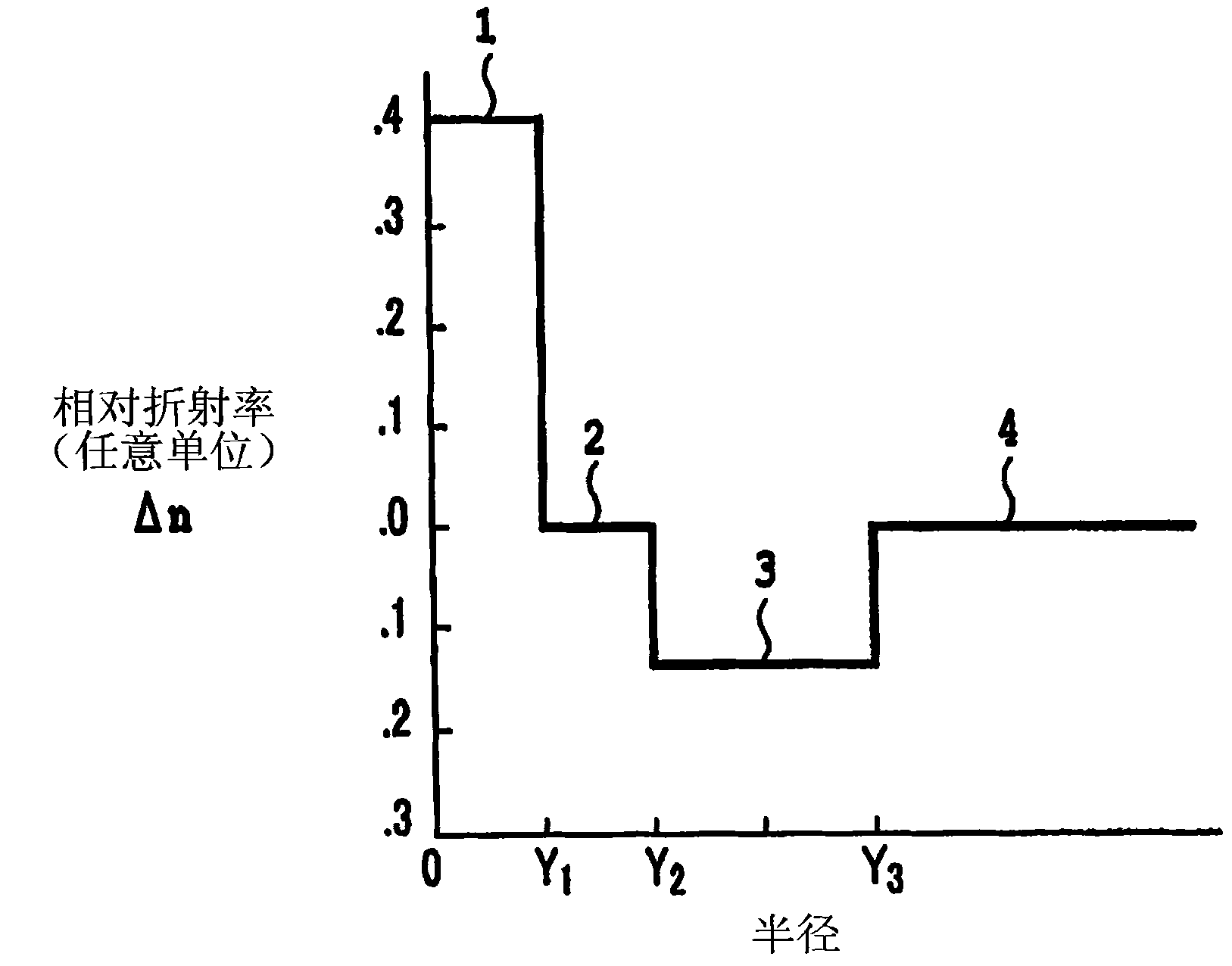
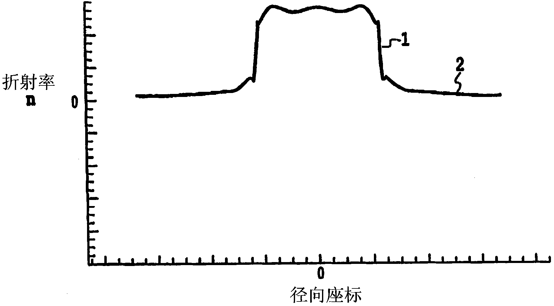
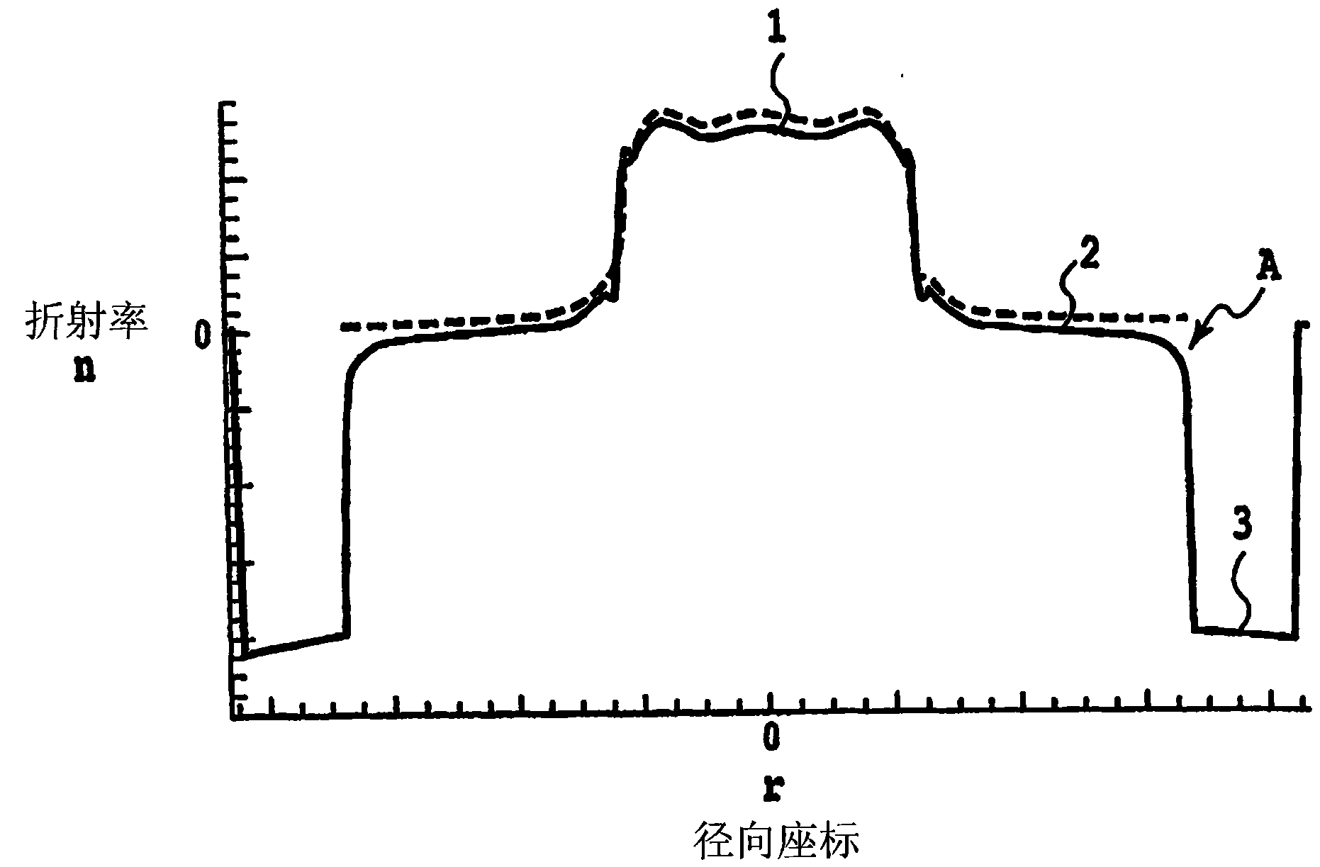
[0059] The core member was manufactured by the method described above. Figure 8 A shows the refractive index profile of the core member. In this core member, the relative refractive index difference Δ1 in the core region was 0.38%, and the relative refractive index difference Δ2 in the inner cladding region was substantially 0. In addition, the core member is heat-treated in a chlorinated atmosphere so that about 0.1% to 0.2% of residual chloride remains in the core member as an unintentionally added impurity.

[0060] Next, the channel region is deposited on the outer surface of the core member by the OVPO method. The channel region is formed by stacking about 200 layers of fluorine-containing quartz glass. Each fluorine-containing quartz glass layer had a thickness of approximately 0.02 mm and was formed by depositing 0.02 mm-thick fluorine-containing quartz glass particles on the core member while rotating the core member about the central axis of the core region. Fluor...

Embodiment 2

[0071] A core member was produced by the same method as in Example 1. The core member has such Figure 8 The refractive index profile is shown and has the same characteristics as the fiber of Example 1.

[0072] Next, a porous layer for the channel region was deposited on the outer surface of the core member by the OVPO method. The channel region is formed by stacking about 200 porous glass layers formed of quartz glass. Each porous glass layer has a thickness of about 0.04 mm, and is formed by depositing quartz glass particles having a thickness of 0.04 mm on the core member while rotating the core member about the central axis of the core region. Quartz glass particles are made by adding silicon tetrachloride (SiCl 4 ) gas is supplied to the oxyhydrogen flame and synthesized. Initially 40 porous glass layers were deposited while the flow rate of hydrogen gas supplied to the oxyhydrogen flame was increased layer by layer by a predetermined amount. The density of the init...


PUM

PropertyMeasurementUnit
thicknessaaaaaaaaaa
thicknessaaaaaaaaaa

Abstract

An optical fiber capable of suppressing an increase of a transmission loss after exposure of the optical fiber to hydrogen or deuterium is provided. The optical fiber has a core region (1), an inner cladding region (2) surrounding the core region, a trench region (3) surrounding the inner cladding region, an outer cladding region (4) surrounding the trench region, and a refractive index varying region arranged between the inner cladding region and the trench region, the refractive index varying region (10) having a refractive index gradually increasing from the trench region to the inner cladding region.

Description

technical field [0001] The present invention relates to a single-mode optical fiber having a channel-type index profile, an optical fiber preform for manufacturing the optical fiber, and a method for manufacturing the optical fiber preform. Background technique [0002] US Patent No. 4,852,968 discloses a single-mode fiber in which bend sensitivity is reduced to improve bend tolerance. Such as figure 1 As shown, the optical fiber has a core region 1 , an inner cladding region 2 surrounding the core region 1 , a channel region 3 surrounding the inner cladding region 2 and an outer cladding region 4 surrounding the channel region 3 . The refractive index curve of the optical fiber has a channel-type refractive index curve in which the refractive index of the channel region disposed between the inner cladding region and the outer cladding region is lower than the refractive index of the inner cladding region and the refractive index of the outer cladding region, such as figur...

Claims


Application Information

Patent Timeline
Patent Type & Authority Patents(China)
IPC IPC(8): G02B6/036G02B6/02C03B37/012C03B37/018
CPCC03B2201/12G02B6/0365C03B37/01413C03B2203/23G02B6/028
Inventor 小山田浩乙坂哲也
Owner SHIN ETSU CHEM IND CO LTD
Features
  • R&D
  • Intellectual Property
  • Life Sciences
  • Materials
  • Tech Scout
  • Unparalleled Data Quality
  • Higher Quality Content
  • 60% Fewer Hallucinations
Learn More