Dispersion Compensation Method and Device

A dispersion compensation and dispersion technology, applied in the field of optical network communication, can solve the problems of inflexible configuration, inability to upgrade smoothly, and high system cost, and achieve the effect of flexible mode configuration and powerful smooth transition upgrade capability

Active Publication Date: 2016-12-14
ZTE CORP
View PDF4 Cites 0 Cited by
  • Summary
  • Abstract
  • Description
  • Claims
  • Application Information

AI Technical Summary

Problems solved by technology

[0006] Aiming at the problems of high system cost, inflexible configuration and inability to upgrade smoothly in the existing dispersion monitoring technology in the related art, the present invention provides a dispersion compensation method and device to solve at least one of the above problems

Method used


Image

  • Dispersion Compensation Method and Device
  • Dispersion Compensation Method and Device
  • Dispersion Compensation Method and Device

Examples


Embodiment 1

[0054] This embodiment relates to an apparatus and method capable of centrally controlling the dispersion of an optical transport network (Optical Transport Network, OTN for short) equipment network.

[0055] The purpose of this embodiment is to overcome the problem of monitoring dispersion and chromaticity in the prior art and the problem that the TDC regulation time on the channel exceeds the threshold. In order to achieve the above purpose, this embodiment provides the following technical solutions:

[0056] Such as Figure 4 As shown, the dispersion compensation device of this embodiment includes: a dispersion locker 40 , a dispersion detector 42 , a dispersion detection controller 44 , a dispersion compensation controller 46 , a dispersion compensator 48 and a dispersion fine-tuning controller 50 .

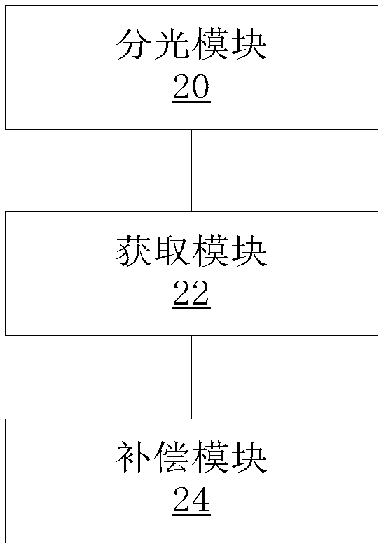
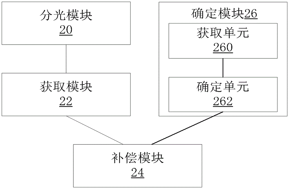
[0057] Wherein, the above-mentioned dispersion locker 40 is equivalent to figure 2 and / or image 3 In the spectroscopic module 20, the dispersion compensator 48 is equiv...

Embodiment 2

[0070] This embodiment provides a dispersion compensation method, which is used to implement centralized wavelength adjustment control. It should be noted that the method in this embodiment can be implemented based on the modules in Embodiment 1. Such as Figure 5 As shown, the method includes:

[0071] Step S502, start;

[0072] Step S504, the dispersion detection controller issues a command to the dispersion detection module to detect the wavelength;

[0073] Step S506, the dispersion detection module filters out a signal of a specified wavelength;

[0074] Step S508, the filtering is successful? If it fails, go to step S510, and if it succeeds, go to step S512;

[0075] In step S510, an alarm is reported, and the adjustment is completed.

[0076] Step S512, the dispersion detection module samples and calculates the dispersion value of the specified wavelength signal;

[0077] Step S514, sending dispersion information to the detection controller;

[0078] Step S516, the...

Embodiment 3

[0098] This embodiment provides a dispersion compensation device, such as Image 6 As shown, it includes: an optical splitter 60 , an optical splitting unit 62 , a dispersion detector 42 , a dispersion detection controller 44 , a dispersion compensation controller 46 , a dispersion compensator 48 and a dispersion fine-tuning controller 50 . Wherein, the optical splitter 10 divides the optical signal on the line into two beams according to a certain ratio, one beam is sent to the optical splitting unit 62 , and the other beam is sent to the dispersion detector 42 . Through the user interface, the dispersion detection controller 44 sends a signal of a specified wavelength to realize the dispersion detection, and the dispersion detection controller 44 sends a command to the dispersion detector 42 through the communication link, and the dispersion detector 42 controls the filter unit 420 to output the wavelength for lambda N The dispersion value is calculated by the detection uni...


PUM


Abstract

The present invention provides a dispersion compensation method and device, wherein the method includes: dividing the optical signal to be transmitted into a first optical signal and a second optical signal, wherein the first optical signal is used to obtain the dispersion information, the second optical signal is used to transmit service data; the dispersion information is acquired from the first optical signal; and the first dispersion is performed on the second optical signal according to the acquired dispersion information compensate. The above-mentioned technical solution provided by the present invention can solve the problems of high system cost, inflexible configuration, and inability to upgrade smoothly in related technologies, and then achieve flexible control of business between channels without being restricted by whether to transmit services Switching and simultaneous control realize flexible mode configuration, centralized control or distributed control can be used to realize seamless embedding of the system, and have a powerful effect of smooth transition and upgrade capabilities.

Description

technical field [0001] The present invention relates to the technical field of optical network communication, in particular to a dispersion compensation method and device. Background technique [0002] Dispersion refers to the phenomenon that polychromatic light is decomposed into monochromatic light to form a spectrum. Dispersion will cause signal deterioration in long-distance optical transmission systems, and the impact will become greater with the increase of transmission distance and transmission rate. Before the 40Gbit / s rate system appeared, the optical transmission system generally adopted a fixed dispersion compensation module (Dispersion Compensation Module, DCM for short) in the multiplex section to implement dispersion compensation. For 40G and above rate systems, due to the insufficient compensation accuracy of the dispersion compensation module, the mismatch between the dispersion slope compensation and the optical fiber, the environmental temperature change ha...

Claims


Application Information

Patent Timeline
Patent Type & Authority Patents(China)
IPC IPC(8): H04B10/2513H04L1/00
Inventor 李荆晶邹红兵
Owner ZTE CORP
Why Eureka
Try Eureka