A treatment process for industrial flue gas

A technology of industrial flue gas and treatment process, which is applied in the direction of combustion product treatment, waste gas exhaust device, combustion method, etc., can solve the problem of unrecovered flue gas purification process resistance drop, etc., to increase flue gas purification efficiency and flexibly switch , Reduce the effect of drag drop

Active Publication Date: 2019-05-17
CHINA PETROLEUM & CHEM CORP
View PDF5 Cites 0 Cited by
  • Summary
  • Abstract
  • Description
  • Claims
  • Application Information

AI Technical Summary

Problems solved by technology

Inquiring relevant information, none of the inventions related to reducing the resistance drop of the flue gas purification process were retrieved.

Method used


Image

  • A treatment process for industrial flue gas

Examples


Embodiment 1

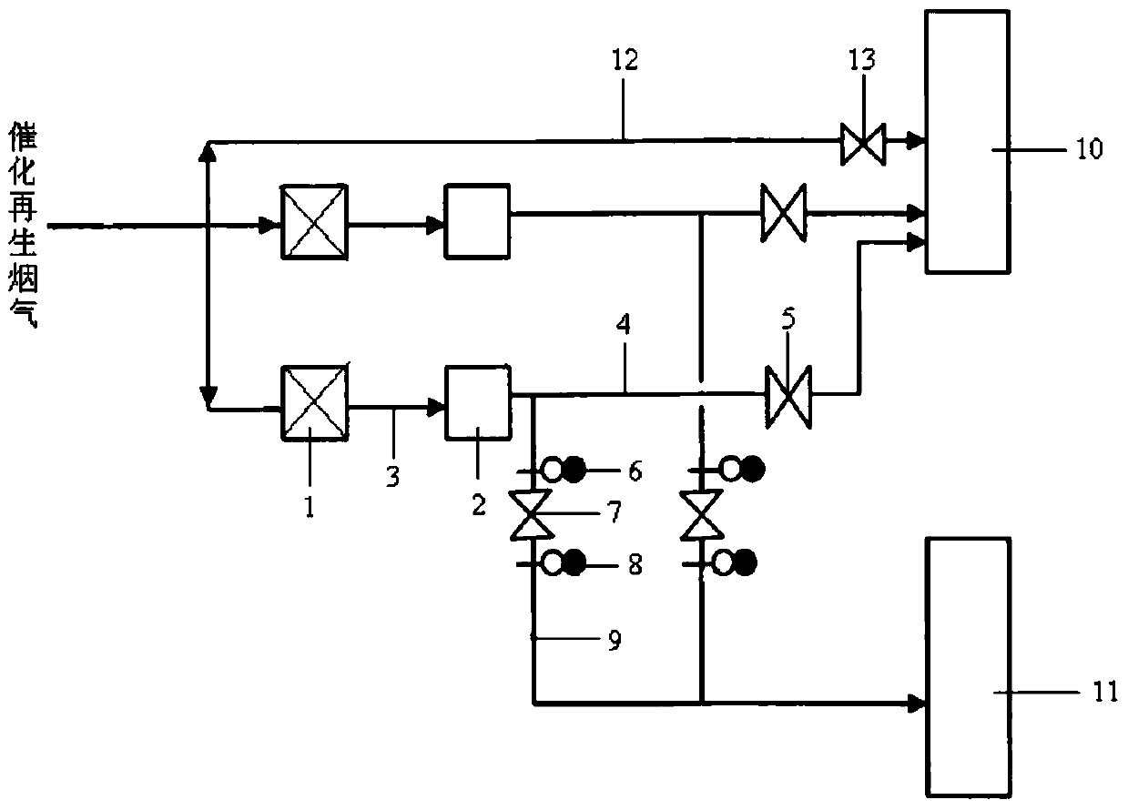
[0025] combined with figure 1 For the flue gas pipeline of the present invention, the process of treating catalytic cracking regenerated flue gas and the operation method when some equipment in the flue gas pipeline needs to be overhauled:

[0026] The process of the two sets of flue gas pipelines processing the regenerated flue gas: the regenerated flue gas from the catalytic cracking unit enters the two sets of flue gas pipelines, and the operation mode of the regenerated flue gas in the two sets of flue gas pipelines is: first enter The flue gas pipeline I passes through the water-sealed tank, and then enters the waste heat recovery boiler to recover the heat energy and chemical energy in the regeneration flue gas; if the regeneration flue gas does not need to be purified, the regeneration flue gas enters the chimney through the flue gas pipeline II to be emptied; When the flue gas needs to be purified, close the isolation valve I on the flue gas pipeline II, open the isola...

Embodiment 2

[0033] The total amount of regenerated flue gas of a 1.05 million tons / year catalytic cracking unit is 160000Nm 3 / h, set up two waste heat recovery boilers to recover flue gas energy, and the flue gas needs to be further purified before being discharged into the atmosphere. figure 1 The design of the process flow from the waste heat recovery boiler outlet to the inlet of the flue gas purification equipment adopts the flow design of the drawing, and the resistance drop of the corresponding piping system is less than 1KPa. If water-sealed tanks are designed to separate the outlet of the waste heat recovery boiler and the inlet of the flue gas purification equipment, the resistance drop of the piping system will increase by about 2-4KPa.

Embodiment 3

[0035] The total amount of regenerated flue gas of a catalytic cracking unit is 138000Nm 3 / h, set up two waste heat recovery boilers to recover flue gas energy, and the flue gas needs to be further purified before being discharged into the atmosphere; there is another 3000Nm 3 / h Hydrogen sulfide incineration tail gas needs to be further purified before being discharged into the atmosphere, according to the attached figure 1 The principle design of the process flow, from the outlet of the waste heat recovery boiler (incinerator) to the inlet of the flue gas purification equipment adopts the flow design of the drawing, and the corresponding resistance drop of the pipeline system is less than 1KPa. If water-sealed tanks are designed to separate the outlet of the waste heat recovery boiler (incinerator) and the inlet of the flue gas purification equipment, the resistance drop of the pipeline system will increase by about 2 to 5KPa.


PUM


Abstract

The invention discloses a process for treating industrial exhaust gas, wherein industrial exhaust gas is pumped into an exhaust gas purification device through at least a group of exhaust gas pipeline to purify and evacuate or to be pumped into a chimney to evacuate, an exhaust gas pipeline I is connected with a waste heat recovery boiler, an exhaust gas pipeline which comes out from the waste heat recovery boiler is divided into an exhaust gas pipeline II and an exhaust gas pipeline III, the exhaust gas pipeline II is connected with the chimney, the exhaust gas pipeline III is connected with the exhaust gas purification device, a water seal tank is arranged on a pipeline of the exhaust gas pipeline I, a partition valve I is arranged on a pipeline of the exhaust gas pipeline II, a partition valve II is arranged on the exhaust gas pipeline III, a blind plate I is arranged on one end of the exhaust gas pipeline II lead to the waste heat recovery boiler, and a blind plate II is arranged on one end of the exhaust gas pipeline II lead to the exhaust gas purification device. The process for treating the industrial exhaust gas can effectively reduce exhaust gas resistance drop, and is convenient for equipment maintenance when exhaust gas is purified and treated.

Description

technical field [0001] The invention relates to a process for treating industrial flue gas, which belongs to the field of flue gas purification treatment. Background technique [0002] With the increase of my country's demand for energy, the emissions of SOx and NOx formed in the process of coal burning, fuel oil and oil refining are increasing day by day. SOx and NOx are the main air pollutants, and SOx and NOx in the atmosphere seriously endanger the human living environment in the form of acid rain. Over the years, the control of flue gas pollutants has received extensive attention at home and abroad, and has become an important part of protecting the environment and controlling air pollution. In the refining catalytic cracking unit, the regenerated flue gas is usually discharged directly after passing through the waste heat recovery system, but the exhausted flue gas contains a large amount of harmful substances such as SOx, NOx, and catalyst dust particles, which has b...

Claims


Application Information

Patent Timeline
Patent Type & Authority Patents(China)
IPC IPC(8): F23J11/00F23J15/00
Inventor 杜建文潘罗其颜刚杨锦明黄伊辉
Owner CHINA PETROLEUM & CHEM CORP
Why Eureka
Try Eureka