Network optimization flow control method, device and system

A network optimization and flow control technology, applied in the field of communication, can solve the problems of large amount of calculation, difficulty of optimization scheme, increase of time spent in collecting information and calculation, etc., so as to achieve the effect of improving real-time performance and reducing the amount of calculation.

Inactive Publication Date: 2012-03-21
HUAWEI TECH CO LTD
View PDF3 Cites 1 Cited by
  • Summary
  • Abstract
  • Description
  • Claims
  • Application Information

AI Technical Summary

Problems solved by technology

[0004] However, the above-mentioned existing technology has the following technical defects: since the solution is solved in a centralized manner, in the actual network, the solution to the optimal problem requires a lot of network state information, especially when the network scale expands, the information demand varies with the number of nodes As the number increases exponentially, the time it takes to collect information and calculate will increase sharply, and the amount of calculation is too large, making it difficult for network nodes to respond in real time, which brings great difficulty to the implementation of optimization schemes

Method used


Image

  • Network optimization flow control method, device and system
  • Network optimization flow control method, device and system
  • Network optimization flow control method, device and system

Examples


Embodiment 1

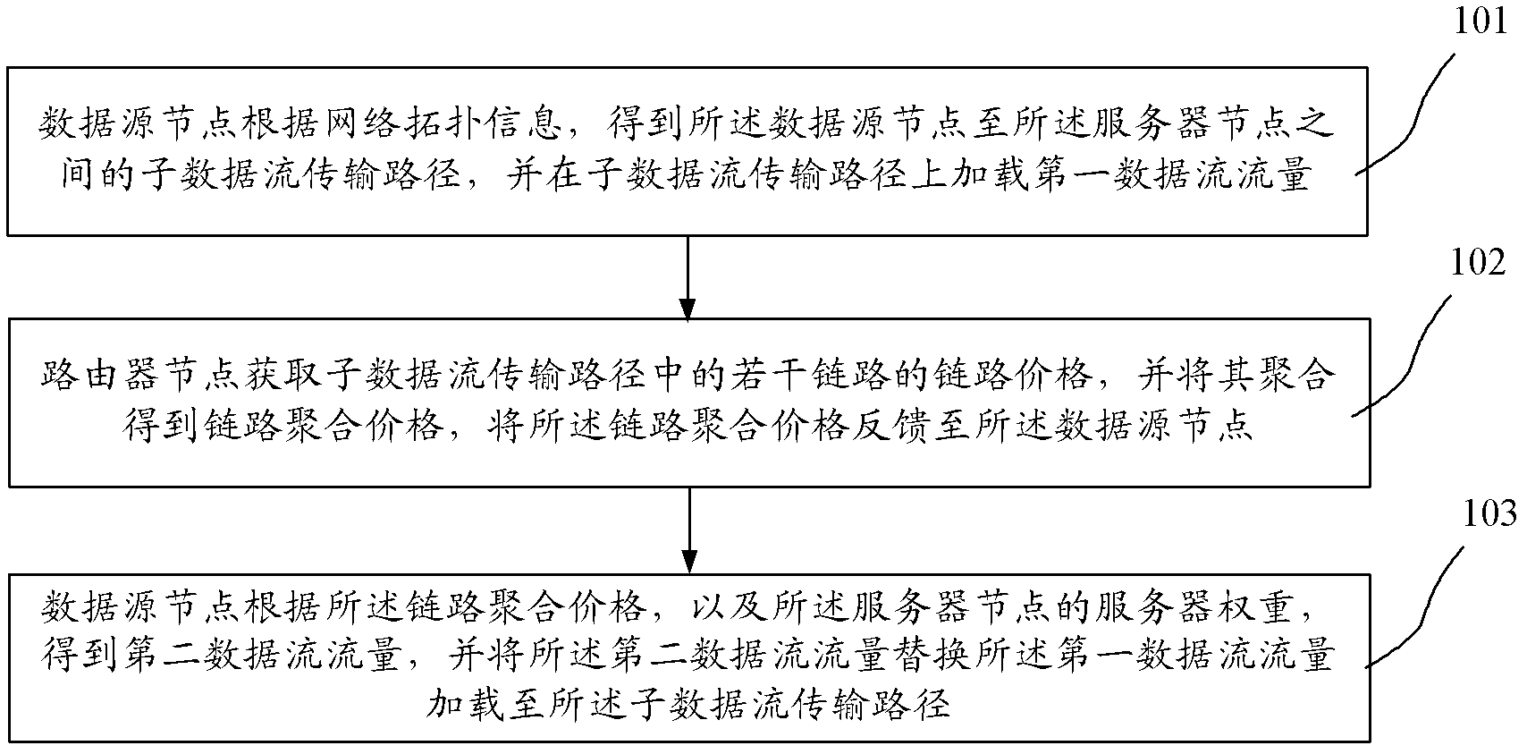
[0035] figure 1 It is a schematic flowchart of Embodiment 1 of the network optimization flow control method of the present invention, wherein the network may include data source nodes, router nodes, and server nodes; and, there is a link between two adjacent router nodes and the two Adjacent router nodes form a link control module. Such as figure 1 As shown, the flow control method of this embodiment may include the following steps:

[0036] Step 101, the data source node obtains the sub-data flow transmission path between the data source node and the server node according to the network topology information, and loads the first data flow on the sub-data flow transmission path;

[0037] For example, compared with the prior art, in the prior art, an optimization processing server separately installed outside the network is used to calculate network traffic, but in this embodiment, the above-mentioned optimization processing server is no longer provided, but directly through t...

Embodiment 2

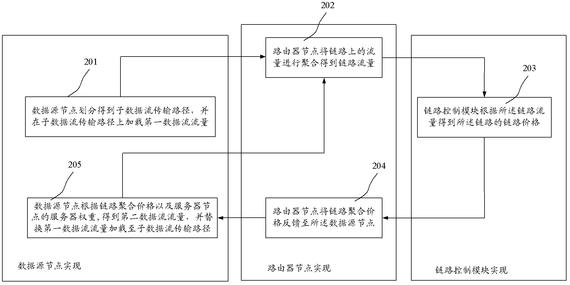
[0051] figure 2 It is a schematic flowchart of Embodiment 2 of the method for network optimization traffic control of the present invention. This embodiment is basically the same as Embodiment 1, and only the steps in Embodiment 1 are described in more detail. Such as figure 2 As shown, the flow control method of this embodiment may include the following steps:

[0052] Step 201, the data source node divides and obtains the sub-data stream transmission path between the data source node and the server node according to the network topology information, and loads the first data stream traffic on the sub-data stream transmission path;

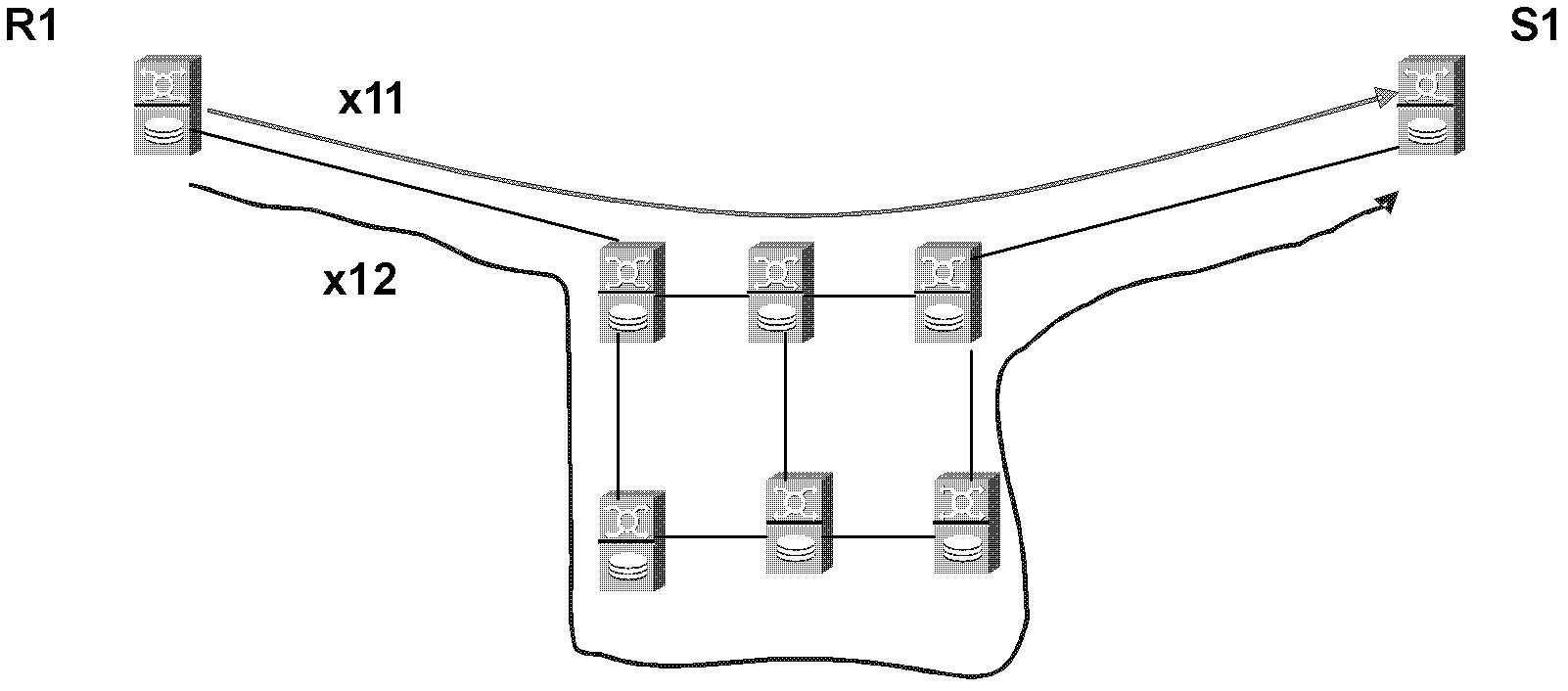
[0053] For example, see image 3 as shown, image 3 It is a schematic diagram of division of transmission paths of sub-data streams in Embodiment 2 of the network optimization flow control method of the present invention. There may be multiple data flow transmission paths between the data source node R1 and the server node S1, image 3 Two ...

Embodiment 3

[0099] Figure 9 It is a schematic structural diagram of Embodiment 1 of the network optimization flow control device of the present invention. The network optimization flow control device of this embodiment can be the data source node described in any embodiment of the present invention, and can execute the data source node described in any embodiment of the present invention. Network optimization flow control method.

[0100] This embodiment briefly introduces the structure of the device, and the specific functions and execution principles of each module can be referred to in the method embodiment. Such as Figure 9 As shown, the device may include an initial loading module 91 , a feedback receiving module 92 and a flow regulating module 93 .

[0101] Wherein, the initial loading module 91 can obtain the sub-data stream transmission path between the data source node and the server node according to the network topology information, and load the first data stream traffic on...


PUM


Abstract

Embodiments of the invention provide a network optimization flow control method, device and system, wherein the method includes the steps that a data source node obtains a sub-data flow transmission path from the data source node to a sever node, and loads a first data flow amount onto the sub-data flow transmission path; a router node aggregates link prices of a plurality of links on the sub-data flow transmission path to obtain link aggregated price and feeds the link aggregated price back to the data source node; and the data source node obtains a second data flow amount according to the link aggregated price and server weight of the server node and loads the second data flow amount instead of the first data flow amount onto the sub-data flow transmission path. Embodiments of the invention greatly reduce calculation amount, and improves instantaneity of network optimization.

Description

technical field [0001] The invention relates to communication technology, in particular to a network optimization flow control method, device and system. Background technique [0002] Traditional Internet Service Providers (Internet Service Providers, referred to as: ISPs) mainly provide Internet connections. In terms of network optimization functions, they mainly solve traffic engineering (TE) problems, designate optimal paths for traffic, and minimize network congestion. The performance of the network is the optimization goal; while the content provider (Content Provider, referred to as: CP) mainly provides users with the content they need, provides users with reasonable resources, and solves the problem of server selection (SS). optimize the target. If the optimization of ISP and CP is combined to perform joint optimization (JO) of TE and SS, the optimal solution of the entire network can be obtained, and end-to-end delay can be minimized while minimizing link congestion...

Claims


Application Information

Patent Timeline
Patent Type & Authority Applications(China)
IPC IPC(8): H04L12/56H04L12/24H04L47/41
CPCH04L12/56H04L45/12H04L12/24H04L45/10
Inventor 项炎平文刘飞
Owner HUAWEI TECH CO LTD
Why Eureka
Try Eureka