

Superhard material tool bit with high surface abrasive resistance and manufacturing method thereof
A technology of superhard materials and manufacturing methods, which is applied in the field of superhard material cutter heads, and can solve the problems of smaller thickness dimensions, large changes in workpiece machining dimensions, and drill core jamming inside the drill barrel, etc.
Inactive Publication Date: 2012-03-28
山东日能超硬材料有限公司
View PDF6 Cites 13 Cited by
- Summary
- Abstract
- Description
- Claims
- Application Information
AI Technical Summary
Problems solved by technology
[0003] The cutter head prepared by this general process is characterized by a single-piece segment with uniform metal bond composition. The cutter head is prone to two problems during the working process: ① the metal bond sintered carcass itself will gradually wear and thin, As a result, the thickness of the cutter head becomes smaller, which is often reduced to the same thickness as the steel matrix; ② After the cutter tooth carcass is worn, its holding force on the superhard abrasive grains is reduced, which will cause the superhard abrasive grains
Method used
View moreImage
Smart ImageViewing Examples

Examples
 PUM
 Abstract
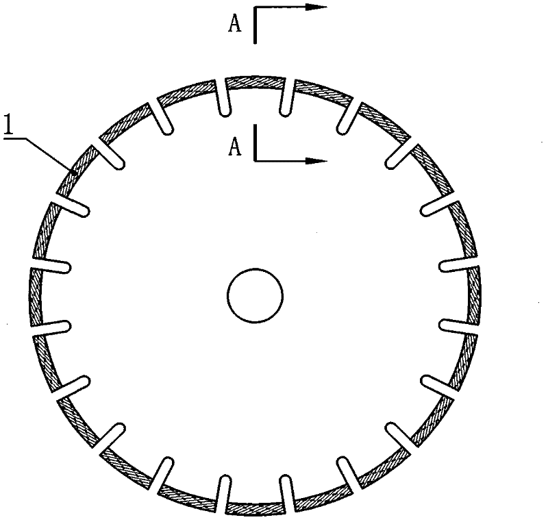
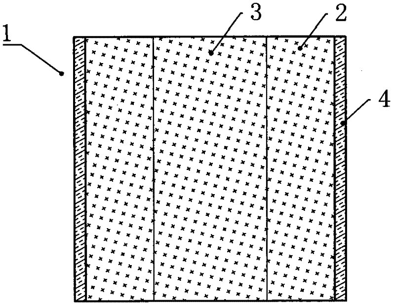
The invention discloses a superhard material tool bit with high surface abrasive resistance and a manufacturing method thereof. The superhard material tool bit with the high surface abrasive resistance comprises a tool bit, and the side surface of the tool bit is provided with a hard abrasion resistant phase. The hard abrasion resistant phase is arranged on the side surface of the tool bit, therefore, the abrasive resistance of the surface of the tool bit is greatly improved, the casing metal at the inner layer is protected against abrasion, the thickness size of the tool bit is maintained, and a stable and continuous machining process is ensured. The heat-resisting inoxidizability of the tool bit is ensured, and oxidation and invalidation of the casing metal caused by a great deal of frication heat generated during machining can be effectively avoided, thereby the mechanical hold of the casing to superhard abrasive material is effectively enhanced, and the machining efficiency of the tool bit is improved, and the service life of the tool bit is prolonged.
Description
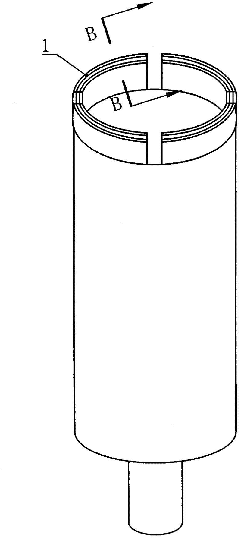
technical field [0001] The invention relates to a superhard material cutter head (also known as working tooth) manufactured by sintering, mainly relates to the superhard material cutter head in the superhard material cutting / drilling tool, and also relates to the manufacture of the superhard material cutter head method. Background technique [0002] At present, most of the structural types of superhard material products (saw blades and engineering thin-walled drills) used to process stone, reinforced concrete and ceramics are sintered segmental working teeth, and a few are circumferential continuous teeth. The production process of the section cutter head is usually to mix the superabrasive (diamond or cubic boron nitride) with several kinds of elemental metal powder or pre-alloy powder, and then cold-press it into a block of the required shape and size on the cold-press forming equipment. Body, hot-pressed and sintered into a finished segment with high density and certain ...
Claims
Login to View More Application Information
Patent Timeline
 IPC IPC(8): B28D1/02B28D1/14B22F7/04
Inventor陈涛
Owner山东日能超硬材料有限公司