Airfoil transformation mechanism of submarine aircraft

A diving aircraft and wing technology is applied in the field of the submersible aircraft wing changing mechanism, which can solve the problems such as unfavorable underwater navigation of the diving aircraft, low skin stiffness and air velocity pressure that cannot meet the flying requirements of the diving aircraft, and large resistance, and the like. The effect of large resistance, increase of maximum speed pressure, and reduction of water-facing area

Inactive Publication Date: 2012-03-28
NANCHANG HANGKONG UNIVERSITY
View PDF9 Cites 11 Cited by
  • Summary
  • Abstract
  • Description
  • Claims
  • Application Information

AI Technical Summary

Problems solved by technology

[0006] Because the wing of the diving plane is relatively large, if the ordinary rigid retractable wing is used, the lateral dimension of the aircraft fuselage will be large to accommodate the retracted wing, which is not conducive to the underwater navigation of the diving plane.
However, when the ordinary folding wing method is adopted, the cross-se

Method used


Image

  • Airfoil transformation mechanism of submarine aircraft
  • Airfoil transformation mechanism of submarine aircraft
  • Airfoil transformation mechanism of submarine aircraft

Examples


Embodiment Construction

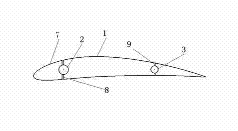
[0014] Among the figure 1 is the second half of the wing rib fixed on the front and rear spars by two front and rear rotating shafts, which can rotate relative to the spar in the horizontal plane by the rotating shafts.

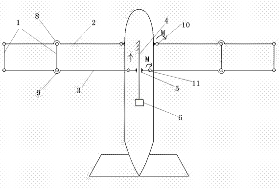
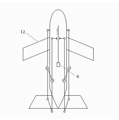
[0015] Figure 2 is the front main beam of the wing fixed on the fuselage. There is a z-axis rotating shaft at the wing heel where it intersects with the fuselage to divide the wing beam into inner and outer parts. The outer part of the wing beam can rotate around the shaft 90 degrees, the spar is parallel to the longitudinal axis of the fuselage after the rotation is completed.

[0016] 3 in the figure is the rear main beam of the wing fixed on the fuselage. There is a z-axis direction rotating shaft at the wing heel where it intersects with the fuselage and divides the wing beam into two sections, the outer section of the wing spar and the fuselage. The wing front spar can rotate 90 degrees around the rotating shaft together, and the rear spar is parallel to...


PUM


Abstract

The invention relates to an airfoil transformation mechanism of a submarine aircraft. A motor is connected in a fuselage, the motor is connected with a screw rod, the screw rod is parallel to the longitudinal axis of the fuselage at the center of the fuselage, a sliding block is connected to the screw rod, the inner section of a back beam of airfoils is in rigid connection with the sliding block, the inner section of the back beam of the airfoils is connected with the outer section of the back beam of the airfoils through a rotating shaft, a front beam of the airfoils is parallel to the back beam of the airfoils, the inner section of the front beam of the airfoils is connected with the wall of the fuselage, and the outer end part of the front beam of the airfoils and the outer end part of the back beam of the airfoils are connected through a front half section wing rib and a back half section wing rib. The airfoil transformation mechanism of the submarine aircraft has the technical effects that symmetrical wing-shaped hydrofoils arranged below the fuselage can produce downward lifting force during submerging, thereby ensuring the submerging requirement of the submarine aircraft and playing a role like a skid type landing gear when the submarine aircraft takes off from the water surface.

Description

technical field [0001] The invention relates to a wing conversion mechanism, in particular to a diving aircraft wing conversion mechanism. Background technique [0002] A diving plane is an aviation vehicle that can fly in the air and dive underwater. The concept of diving aircraft was first proposed during World War II, because the technical conditions at that time failed to overcome the key difficulties of diving aircraft. In the 1860s, the United States developed the world's first diving plane. The pilot drove him to complete the test flight mission. Although he realized two operating modes of diving and flying, he failed to solve the key problems such as materials and wings. The problem caused his technical parameters to fall short of the Navy's requirements and he was forced to stop research. Recently, the U.S. Advanced Planning Bureau re-proposed the plan of the diving aircraft. They summarized the key difficulties in the development of the diving aircraft, and one ...

Claims


Application Information

Patent Timeline
IPC IPC(8): B60F5/00B64C3/38
Inventor 王云刘伟朱莎
Owner NANCHANG HANGKONG UNIVERSITY
Why Eureka
Try Eureka