Converter alloy charging mechanism

A converter and alloy technology, applied in the manufacture of converters, etc., can solve problems such as easy splashing of red high-temperature steel slag, inhalation of heavy metal dust, personal safety injuries, etc., and achieve the effects of improving the working environment, ensuring safety, and reducing smoke and dust on the job

Inactive Publication Date: 2012-03-28
储鸿文 +2
View PDF3 Cites 4 Cited by
  • Summary
  • Abstract
  • Description
  • Claims
  • Application Information

AI Technical Summary

Problems solved by technology

The time to add the alloy, according to the technical requirements, is to add the alloy during the process of pouring the molten steel, and pour the molten steel while adding the alloy. During the process of pouring the molten steel, red high-temperature steel slag is easy to splash, and a large amount of smoke and heat are generated at the same time. It is easier to add the alloy during this process. Slag splashing occurs, and the elevation difference between the operation platform for putting steel and the mouth of the molten steel tank is 2.6m. In such a working condition, artificial alloying can easily cause smoke and heavy metal dust to be inhaled by the human body, and steel slag splashing can easily cause personal safety accidents, even death event

Method used


Image

  • Converter alloy charging mechanism
  • Converter alloy charging mechanism
  • Converter alloy charging mechanism

Examples


Embodiment Construction

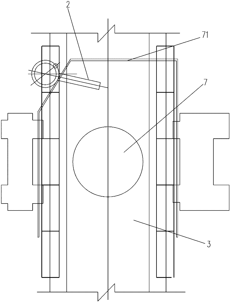
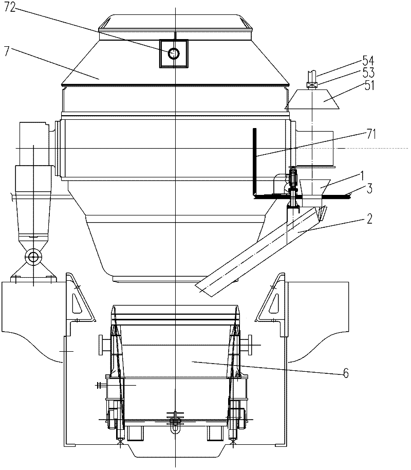
[0021] like Figure 1-3 As shown, the converter alloying mechanism of the present invention includes a converter 7, a steel putting operation platform 3, a molten steel tank 6, a receiving hopper 1, a lower hopper 2, a rocker rotating device, and a dust collection device. The steel putting operating platform 3 is arranged on the converter 7 Around, the rear side, the left side and the right side of the converter 7 are provided with water-cooled coamings 71 respectively, and the water-cooled coamings 71 are fixed on the steel-putting operation platform 3, and the molten steel tank 6 can be moved, and it is moved to the outlet of the converter 7 when blanking. Steel port 72 below.

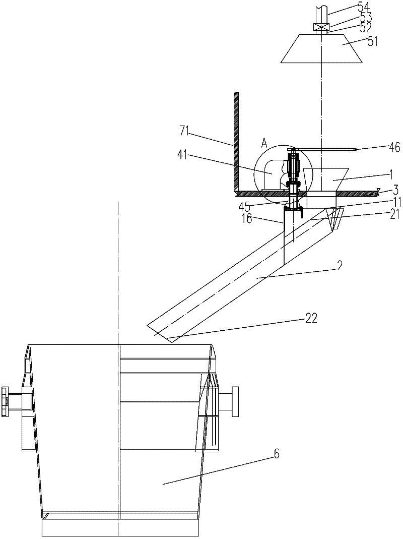
[0022] The receiving hopper 1 is installed on the steel-putting operation platform 3 on the outside of the water-cooled coaming 71, and is located at the rear position on the left side of the converter 7, and the lower hopper 2 is a strip-shaped hopper. to combine Figure 4 As shown, the rocker rot...


PUM


Abstract

The invention discloses a converter alloy charging mechanism, comprising a converter, a steel placing operation platform, a steel water tank, a receiving hopper, a blanking hopper, and a rocker rotary unit, wherein, the steel placing operation platform is arranged around the converter, the back side, left side and right side of the converter are respectively provided with a water cooling coaming plate, the water cooling coaming plates are fixed on the steel placing operation platform, the receiving hopper is arranged on the steel placing operation platform at the outer side of the water cooling coaming plate, the blanking hopper is arranged the lower end of the rocker rotary unit. When in a normal blanking position, the receiving port of the blanking hopper is located just below the discharge port of the receiving hopper, and the blanking port of the blanking hopper is located just above the steel water tank, According to the invention, by respectively arranging the water cooling coaming plate at the back side, left side and right side of the convertor, the invention avoids the slag splashing out to damage people; by arranging the receiving hopper and the blanking hopper, the alloy slips into the steel water tank through the blanking hopper, and no splashing of molten steel is generated, thus the situation that operator is in the face of the splashing of molten steel when the operator directly charges the alloy can be avoided, and the personal injury is avoided.

Description

technical field [0001] The invention belongs to the field of molten steel smelting, in particular to a device for blending alloys into molten steel tanks. Background technique [0002] After the molten steel is smelted in the converter of the converter steelmaking plant, the molten steel is poured from the converter into the molten steel tank, and the composition of the molten steel needs to be fine-tuned, and some different types of alloys are added to the molten steel. The time to add the alloy, according to the technical requirements, is to add the alloy during the process of pouring the molten steel, and pour the molten steel while adding the alloy. During the process of pouring the molten steel, red high-temperature steel slag is easy to splash, and a large amount of smoke and heat are generated at the same time. It is easier to add the alloy during this process. Slag splashing occurs, and the elevation difference between the operation platform for putting steel and the...

Claims


Application Information

Patent Timeline
Patent Type & Authority Applications(China)
IPC IPC(8): C21C5/46
Inventor 储鸿文吴兴良李叶军刘洪许安心王建国
Owner 储鸿文
Why Eureka
Try Eureka