
Back frame and backlight system

A back frame and main splicing technology, which is applied in the field of back frame and backlight system, can solve the problems of high cost of back frame mold, excessive material consumption, high cost of back frame, etc., achieve material saving, simple mold structure, and solve problems that are not easy to fix Effect

Active Publication Date: 2013-07-17
TCL CHINA STAR OPTOELECTRONICS TECH CO LTD
View PDF5 Cites 0 Cited by
  • Summary
  • Abstract
  • Description
  • Claims
  • Application Information

AI Technical Summary

Problems solved by technology

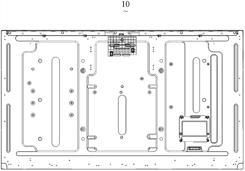
like figure 1 As shown, the back frames 10 in the prior art all adopt an integral back frame, and the integral back frame 10 is usually produced by metal stamping or plastic injection. The integral back frame 10 needs to consume too much material, and the material cost is high.
In addition, the large-sized back frame 10 needs to use relatively large stamping equipment, and the mold corresponding to the back frame 10 has a large size and complex structure, and the cost of the back frame mold is high.
Therefore, the cost of the back frame of the prior art is high

Method used


Image

  • Back frame and backlight system
  • Back frame and backlight system
  • Back frame and backlight system

Examples


Embodiment Construction

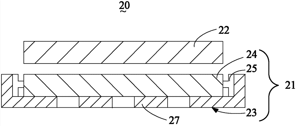
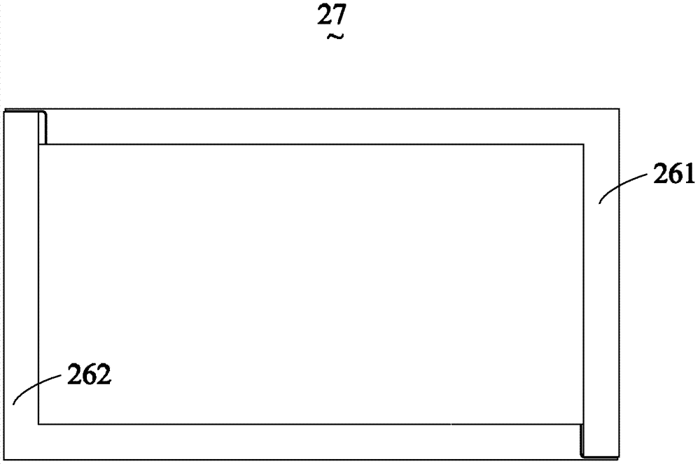
[0057] See Figure 2-3 , figure 2 is a schematic structural view of a flat panel display device according to a first embodiment of the present invention, image 3 is a schematic structural view of the back frame of the flat panel display device according to the second embodiment of the present invention. like figure 2 As shown, the flat panel display device 20 of this embodiment includes: a backlight system 21 and a display panel 22 , the backlight system 21 is disposed on the back of the display panel 22 and provides a light source for the display panel 22 .

[0058] In this embodiment, the backlight system 21 includes a light source 25 , a uniform light mechanism 24 and a back frame 23 . Wherein, the back frame 23 carries a light source 25 and a dodging mechanism 24 . When the backlight system 21 is a side-light type, the uniform light mechanism 24 is a light guide plate; when the backlight system 21 is a direct-light type, the light uniform mechanism 24 is a diffuser ...


PUM


Abstract

A back frame (23) for a flat-panel display device (20). The back frame (23) comprises main assembly components (231, 232, 233, 234, 261, 262, 281, 282, 283), secondary assembly components (235, 236), as well as support brackets (2371, 2372, 2373, 2374, 2375, 2376, 2377, 60) for fixing in place a circuit board (80). The main assembly components (231, 232, 233, 234, 261, 262, 281, 282, 283) are at least two in number, one end of at least one of the main assembly components (231, 232, 233, 234, 261, 262, 281, 282, 283) is provided with assembly parts (2311, 2312, 2361, 2362), and the secondary assembly parts (235, 236) assemble onto the main assembly parts (231,232,233,234,261,262,281,282,283). At least two main assembly components (231, 232, 233, 234, 261, 262, 281, 282, 283) assemble together by means of the corresponding assembly parts (2311, 2312, 2361, 2362); the assembly parts (2311, 2312, 2361, 2362) of at least one of the main assembly components (231, 232, 233, 234, 261, 262, 281, 282, 283) are provided with a reinforcing structure. The support brackets (2371, 2372, 2373, 2374, 2375, 2376, 2377, 60) comprise a support bracket main body (61), a first hanging part (62), a first off-set part (63) and a first flexible flip part (64). Also provided is a backlight system (21). The structural simplicity of the back frame (23) reduces the cost of the mold for the back frame and economizes on materials for the back frame (23), thus reducing the cost of the flat-panel display device (20).

Description

technical field [0001] The invention relates to the field of display technology, in particular to a back frame and a backlight system of a flat panel display device. Background technique [0002] In the prior art, a liquid crystal display device includes a front frame, a panel, and a backlight module, wherein the backlight module includes a back frame, a reflection sheet, a light guide plate, and a lamp group. [0003] Currently, there are various sizes of display panels on the market to meet people's different needs. For example, in the field of television, the size of LCD panels includes 31.5, 42, 46, 48 or 55 inches, and different back frame molds need to be set according to different sizes of LCD panels. [0004] See figure 1 , figure 1 It is a schematic diagram of the structure of the back frame of the liquid crystal display device in the prior art. like figure 1 As shown, the back frames 10 in the prior art all adopt an integral back frame, and the integral back f...

Claims


Application Information

Patent Timeline
Patent Type & Authority Patents(China)
IPC IPC(8): F21V21/00F21V29/00F21S8/00G02F1/13357
CPCG02F1/133308G02F2001/133314H05K7/12G02F1/133314
Inventor 郭仪正萧宇均黄冲程加河阙成文李全杨流洋
Owner TCL CHINA STAR OPTOELECTRONICS TECH CO LTD
Learn More