

Float bowl spiraling type liquid level controller
A liquid level controller, screw-type technology, applied in the direction of liquid level control, non-electric variable control, control/regulation system, etc., can solve the problem of large contact area, large friction force between the guide rod and the inner hole of the buoy, and the problem of the guide rod and the buoy Eliminate problems such as inner hole phase adhesion, achieve high sensitivity and precision, and low friction
- Summary
- Abstract
- Description
- Claims
- Application Information
AI Technical Summary
Problems solved by technology
Method used
Image

Examples
Embodiment Construction
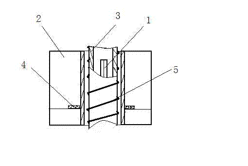
[0010] The present invention will be further described below in conjunction with accompanying drawing:
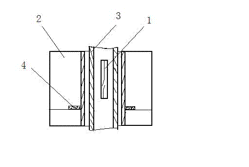
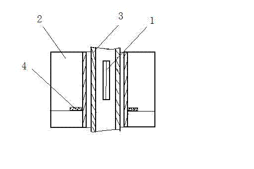
[0011] Such as image 3 As shown, a displacer spiral liquid level controller includes a magnetic reed switch 1, a displacer 2 and a guide rod 3, a magnetic material block 4 is installed in the displacer 2, and the reed switch 1 is installed on a guide made of a non-magnetic material. In the rod 3, the guide rod 3 is installed in the inner hole of the buoy 2. The above-mentioned structure and interconnection relationship are the same as those of the prior art. 5 is spirally wound on the outer diameter of the guide rod 3, the guide wire generally adopts a hydrophobic conductive metal wire, preferably a layer of plastic protective layer is attached to the conductive metal wire, and the present invention spirally winds the guide rod on the outer diameter of the guide rod wire, so that the outer diameter of the guide rod and the wall of the inner hole of the buoy are in point c...
PUM
 Abstract
Description
Claims
Application Information