Shielded cable connecting structure and shielded cable connecting method

A technology for connecting structures and wires, which is applied in the direction of conductive connection, connection, two-part connection device, etc., can solve the problems of low working efficiency, unstable impedance, waste of man-hours, etc., and achieve the effect of simple structure and preventing the impedance from becoming unstable

Active Publication Date: 2012-03-28
YAZAKI CORP
View PDF7 Cites 9 Cited by
  • Summary
  • Abstract
  • Description
  • Claims
  • Application Information

AI Technical Summary

Problems solved by technology

[0012] However, if Figure 7 As shown in (c), the operation of rewinding the conductive tape 108 once unwound on the outer circumference of the plurality of covered electric wires 103 to form the electromagnetic shielding layer 105 again has the problems of wasting man-hours and low work efficiency.
[0013] In addition, when rewinding the conductive tape 108, the fastening of the conductive tape 108 may vary depending on the operator's proficiency.
As a result, the distance between adjacent covered electric wires 103 varies, so there is a possibility that the impedance at the connection portion between the shielded electric wire 101 and the shielded connector becomes unstable, and inherent transmission performance cannot be obtained.

Method used


Image

  • Shielded cable connecting structure and shielded cable connecting method
  • Shielded cable connecting structure and shielded cable connecting method
  • Shielded cable connecting structure and shielded cable connecting method

Examples


Embodiment Construction

[0053] Hereinafter, preferred embodiments of the shielded wire connection structure and the shielded wire connection method according to the present invention will be described in detail with reference to the accompanying drawings.

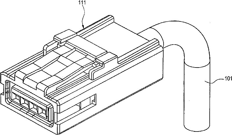
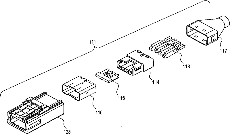
[0054] figure 1 In the shielded wire connection structure involved in the present invention, a Figure 6 A perspective view of an embodiment of the shielded connector 111 of the shielded electric wire 101.

[0055] Such as Figure 6 As shown, the shielded wire 101 includes a plurality of coated wires 103, an electromagnetic shielding layer 105 covering the outer circumference of the plurality of coated electrical wires 103, a braided layer 106 made of conductive metal covering the outer circumference of the electromagnetic shielding layer 105, and a braided layer 106 covering the outer circumference of the electromagnetic shielding layer 105. An insulating sheath 107 around the outer periphery of the braid 106 . The above-mentioned electromagnet...


PUM


Abstract

There is provided a shielded cable connecting structure comprising a shielding layer removed portion where a plurality of covered wires are exposed for connection of connecting terminals to a shield connector and a conductive heat-shrinkable tube which is fittingly mounted on an end portion of an electromagnetic shielding layer which lies adjacent to the shielding layer removed portion and the shielding layer removed portion so as to bind together the plurality of covered wires through heat shrinkage.

Description

technical field [0001] The invention relates to a shielded wire connection structure and a shielded wire connection method for connecting a shielded wire to a connecting terminal of a shielded connector. The electromagnetic shielding layer covering the outer circumference of a plurality of coated wires in the shielded wire is spirally wound on the plurality of coated wires. Formed by the conductive band around the outer circumference of the wire. Background technique [0002] The following Patent Document 1 describes a shielded electric wire which has good bendability and noise resistance and is suitable for wiring of in-vehicle electronic instruments, etc., wherein an electromagnetic shielding layer (shielding layer) is formed by spirally winding the sheathing wire. Formed by the conductive band around the outer circumference of the wire. Figure 6 is a perspective view showing a schematic structure of this type of shielded electric wire. [0003] Figure 6 The illustrated...

Claims


Application Information

Patent Timeline
Patent Type & Authority Applications(China)
IPC IPC(8): H01R13/658H01R24/00H01R43/00
CPCH01R13/6599H01R4/726Y10T29/4921
Inventor 土屋和彦
Owner YAZAKI CORP
Why Eureka
Try Eureka