
Energy-saving method and device based on power grid load dynamic balance

A technology for energy-saving devices and loads, applied in the direction of circuit devices, electrical components, multi-phase network asymmetry reduction, etc., can solve the problem that it is difficult to reflect the unbalanced load line loss, the balance of active power and reactive power, and the lack of load dynamics Balance and other issues to achieve the effect of improving power supply quality, improving power supply reliability, and energy-saving power supply reliability

Active Publication Date: 2014-04-02
BEIJING LUNENG KIRIN ELECTRIC POWER EQUIP
View PDF8 Cites 1 Cited by
  • Summary
  • Abstract
  • Description
  • Claims
  • Application Information

AI Technical Summary

Problems solved by technology

But the patent has a key question on the load balancing method: how to choose which load to switch? How to convert online? How to take into account active and reactive work is not involved
[0010] The relationship between voltage unbalance and unbalanced load is affected by the internal resistance of the power supply, which makes it difficult to reflect the unbalanced load line loss, let alone the balance of active and reactive power; the method of switching 10% load between phases each time lacks theoretical support ; It is also difficult to avoid power outage troubles when switching loads with ordinary composite switches; these are key issues that must be solved for load dynamic balance
[0011] It is precisely because of the lack of load-on-load commutation equipment and the lack of load dynamic balance theory that the static balance method has been used to deal with the problem of load imbalance.

Method used


Image

  • Energy-saving method and device based on power grid load dynamic balance
  • Energy-saving method and device based on power grid load dynamic balance
  • Energy-saving method and device based on power grid load dynamic balance

Examples


Embodiment Construction

[0032] specific implementation method

[0033] Below in conjunction with accompanying drawing illustrate the illustration of concrete implementation method of the present invention:

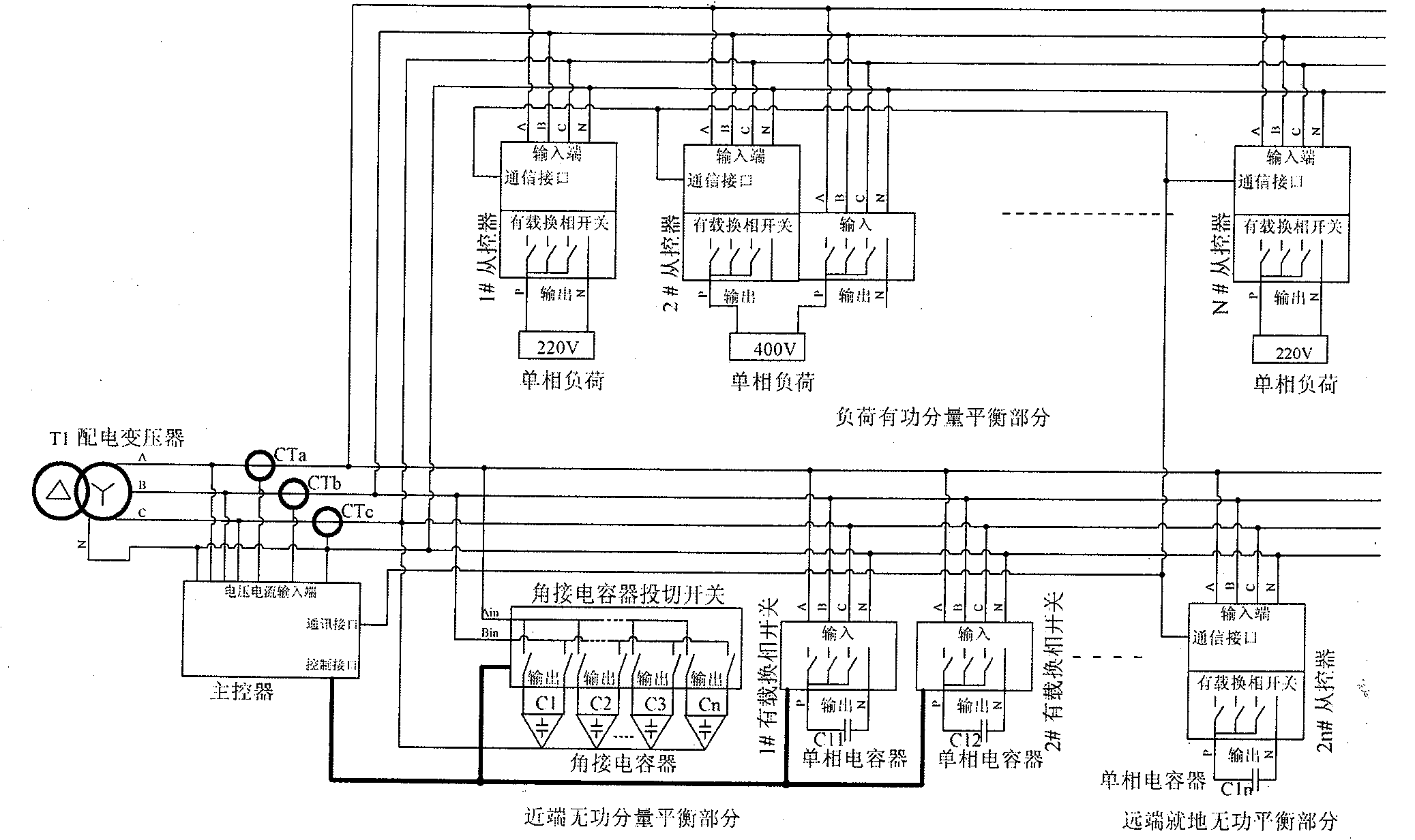
[0034] attached Figure 1 : The structural diagram of the energy-saving system based on the dynamic balance of grid load shows the overall configuration and wiring of the system.

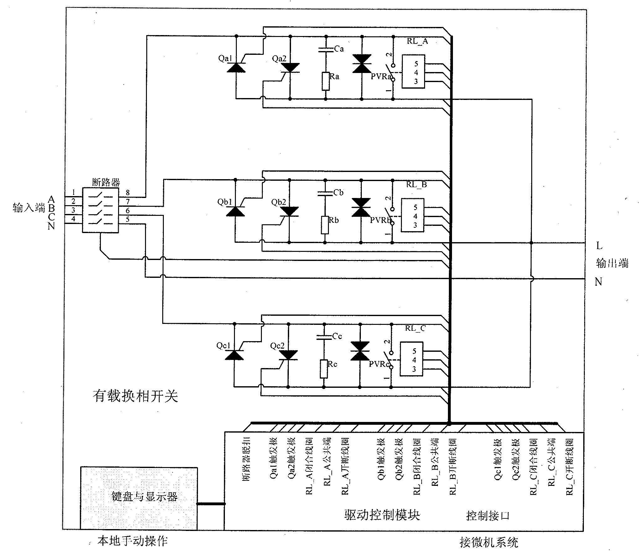
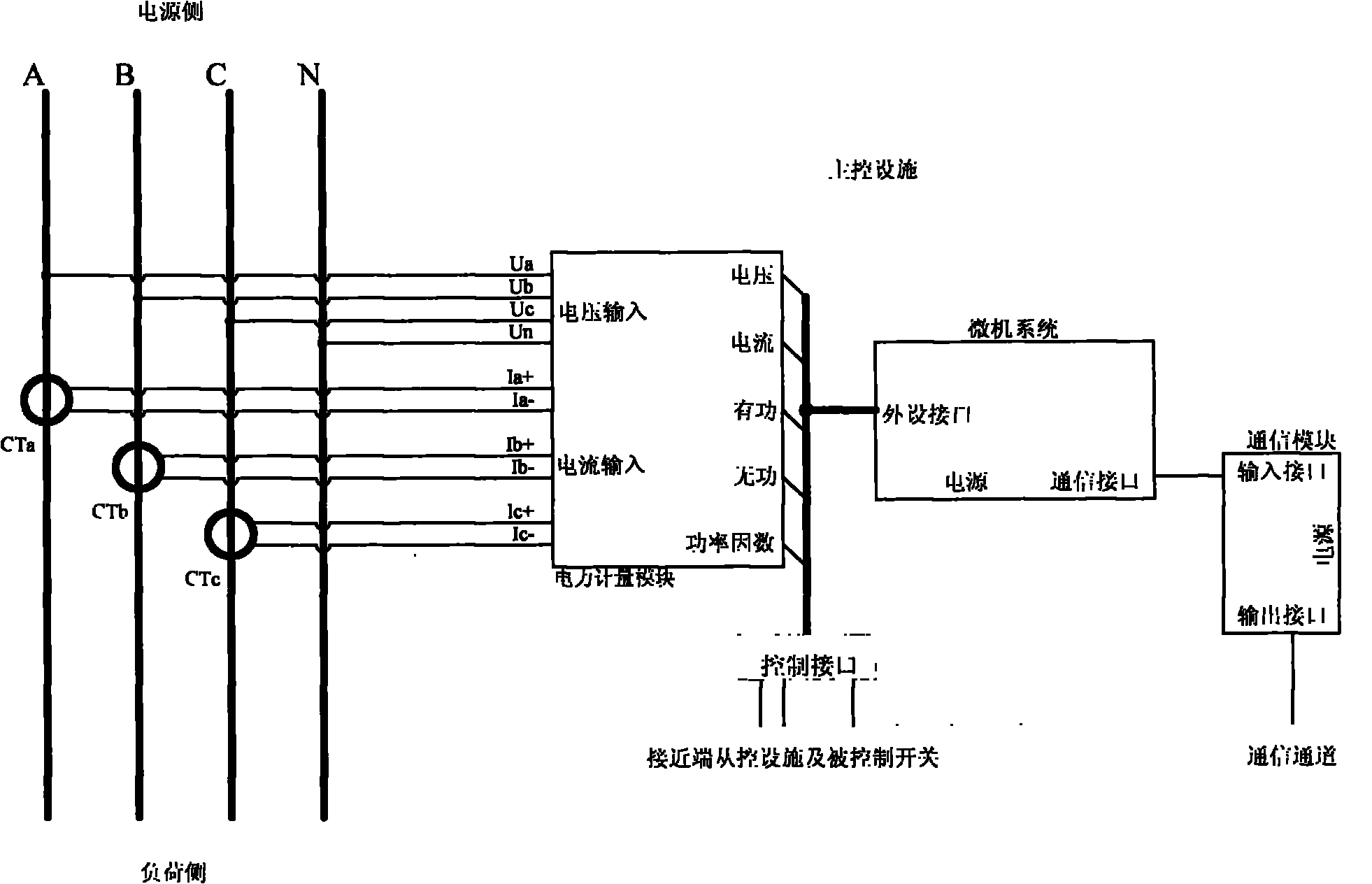
[0035] The load automatic balance power saving device is composed of a master controller and multiple slave controllers. For a three-phase four-wire distribution line composed of one three-phase line and multiple single-phase branches, the transformer outlet to the first Install a master controller on the three-phase line before the single-phase branch, install a slave controller at each branch of the three-phase to single-phase line, and connect the three-phase four-wire system input line to the input terminal of the on-load commutation switch , the single-phase load is connected to the output terminal of the on-load...


PUM


Abstract

The invention relates to a method and device for performing on-load scheduling on a single-phase load in the intelligent power grid field. A master controller is mounted at an input end of a three-phase wire, a secondary controller is mounted at each single-phase branch of the wire, and the master controller exchanges information with the secondary controllers through communication interfaces. When the wire power unbalanced degree is over limit, the master controller optimizes and formulates a control scheme to operate the secondary controllers to convert the single-phase load between the phases; in the conversion process, the load is free from instant power off, and the power grid is free from impact and interference; and therefore, the distribution circuit dynamically runs in a load balance state, the unbalanced consumption problem of the circuit is completely solved.

Description

technical field [0001] The invention belongs to the technical field of smart grid automation, and relates to a method and a device for on-load commutation of electric loads, in particular to a brand-new technology for realizing energy saving by controlling dynamic balance of loads. Background technique [0002] The end users of the power system include a large number of single-phase loads, especially commercial and residential facilities: such as electric heating facilities, air conditioners, electric water heaters, refrigerators, lighting facilities, commercial machinery, computers and various household appliances. The number of them is increasing, the power is increasing, the requirements for power supply reliability and quality are getting higher and higher, and the randomness of power demand is becoming stronger and stronger, which makes the three-phase loads on the low-voltage side of the distribution network different The balance problem is getting worse. [0003] As ...

Claims


Application Information

Patent Timeline
Patent Type & Authority Patents(China)
IPC IPC(8): H02J3/26H02J3/18H02J13/00
CPCY02E40/50Y04S10/22Y04S10/545Y02E40/76Y02E40/30Y02E40/74Y02E40/70Y04S10/50
Inventor 袁淼
Owner BEIJING LUNENG KIRIN ELECTRIC POWER EQUIP
Learn More