Flow uninterruptible method and device based on virtual machine VM (virtual memory) migration

A virtual machine and traffic technology, which is applied in the field of network communication and can solve problems such as the inability of the VM to receive multicast traffic and the interruption of multicast traffic.

Inactive Publication Date: 2012-03-28
NEW H3C TECH CO LTD
View PDF3 Cites 26 Cited by
  • Summary
  • Abstract
  • Description
  • Claims
  • Application Information

AI Technical Summary

Problems solved by technology

After the VM is migrated, because the interface S-CHANNEL B connected after the VM migration has not joined the multicast group, the migrated VM cannot receive the multicast traffic in the multicast group that has joined before the migration, that is, multicast traffic occurs to interrupt

Method used


Image

  • Flow uninterruptible method and device based on virtual machine VM (virtual memory) migration
  • Flow uninterruptible method and device based on virtual machine VM (virtual memory) migration
  • Flow uninterruptible method and device based on virtual machine VM (virtual memory) migration

Examples


Embodiment 1

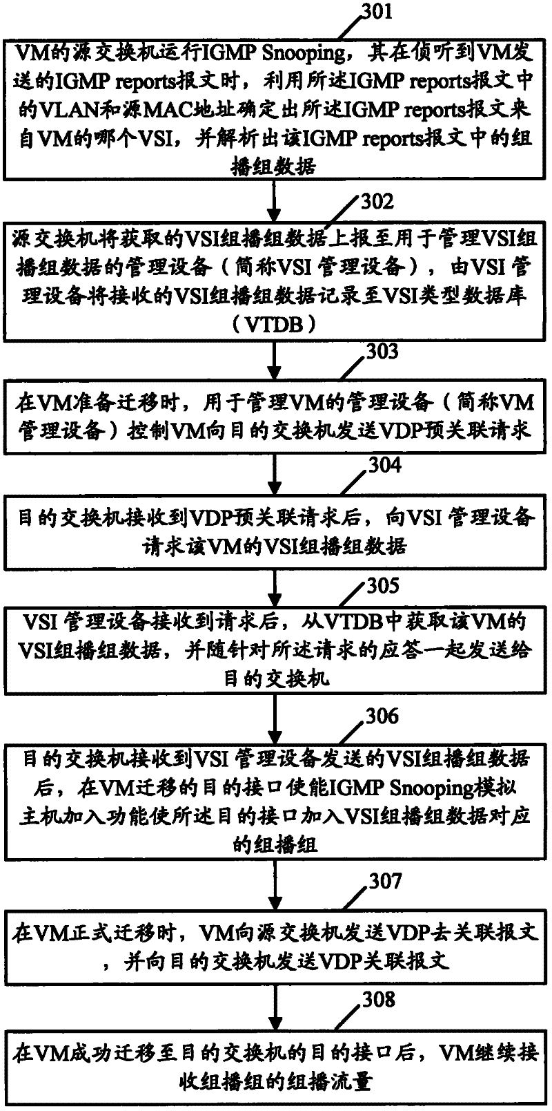
[0034] see image 3 , image 3 The flow chart provided for Embodiment 1 of the present invention. Such as image 3 As shown, the process may include the following steps:

[0035] Step 301, the source switch of the VM runs IGMP Snooping, and when it detects the IGMP reports message sent by the VM, it uses the VLAN and the source MAC address in the IGMP reports message to determine that the IGMP reports message comes from the VM which VSI, and parse out the multicast group data in the IGMPreports message.

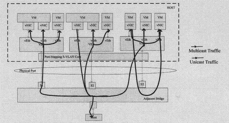
[0036] The VSI is represented through the VM's vNIC. Generally, a VM can contain at least one vNIC, and different vNICs will have different VSIs.

[0037] It can be seen that through step 301, the multicast group data corresponding to all VSIs of the VM can be obtained. Wherein, the multicast group data includes at least the multicast source S and the multicast group G. Taking the VM including VSI1, VSI2 and VSI3 as an example, all VSI multicast group data of the VM as...

Embodiment 2

[0057] Compared with Embodiment 1, in Embodiment 2, the SCUD associated with the VM identifies and records the VSI multicast data of the associated VM, instead of identifying the VSI multicast data of the VM by the switch connected to the VM as in Embodiment 1. .

[0058] see Figure 4 , Figure 4 The detailed flowchart provided for Embodiment 2 of the present invention. Such as Figure 4 As shown, the process may include the following steps:

[0059] Step 401, the source SCUD of the VM runs IGMP Snooping, and when listening to the IGMP reports message sent by the VM, determines the VSI connected to the VM, and identifies the group corresponding to the VSI by analyzing the IGMP reports message sent by the VM broadcast group data.

[0060] The VM is connected to the source SCUD through the VSI. Therefore, when the source SCUD receives the IGMP report sent by the VM, it determines the VSI connected to the VM as the VSI from which the IGMP report message comes.

[0061] com...

Embodiment 3

[0075] Compared with Embodiment 1 and Embodiment 2, in Embodiment 3, the management device of the VM sends the VSI multicast group data to the associated SCUD after VM migration before the VM is migrated to the destination interface of the destination switch. Control the SCUD to send the IGMPreports message for the multicast group in the VSI multicast group data, so that the VM joins the multicast group on the destination interface of the destination switch.

[0076] see Figure 6 , Figure 6 The detailed flowchart provided for Embodiment 3 of the present invention. Such as Figure 6 As shown, the process may include the following steps:

[0077] Step 601, the source SCUD of the VM runs IGMP Snooping, and when listening to the IGMP reports message sent by the VM, determines the VSI connected to the VM, and identifies the group corresponding to the VSI by parsing the IGMP reports message sent by the VM broadcast group data.

[0078] Taking the VM including VSI1 and VSI2 as...


PUM


Abstract

The invention provides flow uninterruptible method and device based on virtual machine VM (virtual memory) migration. The method comprises the following steps: firstly, using internet group management protocol (IGMP) to pry into virtual site interface VSI (vertical speed indicator) multicast group data of a VM in the snooping recognition network; secondly, sending the VSI multicast group data of the VM to a network management side; and thirdly, obtaining the VSI multicast group data of the VM from the network management side before the VM migrates to the purpose interface of a purpose switch, and adding the purpose interface to the multicast group corresponding to the obtained VSI multicast group data so as to lead the VM to continue receiving the multicast flow of the VSI multicast group after the VM migrates to the purpose interface.

Description

technical field [0001] The invention relates to network communication technology, in particular to a method and device for uninterrupted flow based on a virtual machine (VM). Background technique [0002] In the data center network, the introduction of virtualization technology has changed the deployment mode of the data center network. In a physical server (End Station), there is a software entity called Hypervisor. Based on the Hypervisor, multiple VMs on a physical server can share the same hardware system. [0003] On a physical server, each VM includes at least one virtual network interface card (vNIC), and is connected to the physical network interface card of the physical server through the Hypervisor. Wherein, the Hypervisor realizes the connection between the vNIC of the VM and the physical network card of the physical server through a virtual Ethernet bridge (VEB) and / or a virtual Ethernet port aggregation (VEPA). Here, VEB and / or VEPA are commonly referred to as...

Claims


Application Information

Patent Timeline
Patent Type & Authority Applications(China)
IPC IPC(8): H04L12/56H04L12/18H04L45/16
CPCH04L67/38G06F9/45558G06F2009/4557G06F9/4856G06F9/45533H04L12/18H04L12/1877H04L67/131
Inventor 常慧锋
Owner NEW H3C TECH CO LTD
Why Eureka
Try Eureka