Floating positioning device

A floating positioning and limit pin technology, used in the equipment field of the machinery industry, can solve the problems of difficult part positioning and ejecting functions, small effective space, etc., and achieve the effect of preventing dust and increasing life.

Inactive Publication Date: 2012-04-04
芜湖火龙铸造有限公司
View PDF7 Cites 11 Cited by
  • Summary
  • Abstract
  • Description
  • Claims
  • Application Information

AI Technical Summary

Problems solved by technology

[0002] In some mechanical processing plants, it is usually necessary to position the workpiece, and sometimes it is necessary to eject the material, but when processing some smaller parts, if the When it comes to these two methods, becau

Method used


Image

  • Floating positioning device
  • Floating positioning device

Examples


Embodiment Construction

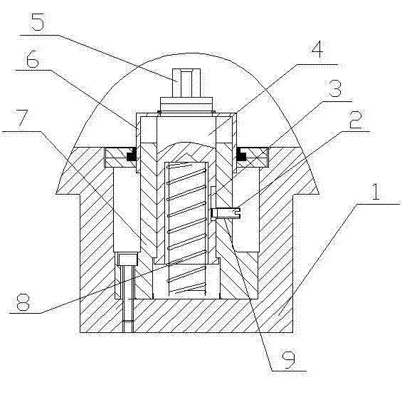
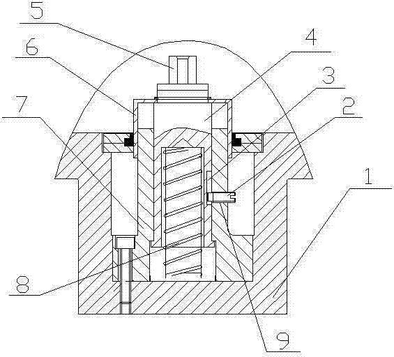
[0010] like figure 1 Said floating positioning device comprises a mounting base plate 1, said mounting base plate 1 is fixedly connected with a circlip 7 for a shaft, and the axial part of the circlip 7 for a shaft is provided with a through hole with a step, and a through hole is provided in the through hole Screw 4, the head of the screw 4 is provided with a positioning pin 5, the bottom of the screw 4 is provided with a blind hole, and a spring 8 is arranged between the installation base plate 1 and the blind hole; There is a protective cover 6; the screw 4 is provided with a limit pin groove 3, and the shaft circlip 7 is provided with a pin hole 9, and the limit pin 2 is installed in the pin hole 9, and one end protrudes from the limit pin in slot 3.

[0011] When the part needs to be positioned, the pin hole of the part is aligned with the positioning pin 5, and the part is fixed with a clamp; when the part needs to be taken out, the clamp is released, the spring...


PUM


Abstract

The invention relates to a floating positioning device, which comprises an installation base plate, wherein an elastic retainer ring for a shaft is fixedly connected to the installation base plate; a through hole with a step is formed on an axis part of the elastic retainer ring for the shaft; a screw is arranged in the through hole; a positioning pin is arranged on the head part of the screw; a blind hole is formed at the bottom of the screw; a spring is arranged between the installation base plate and the blind hole; a protective cover is arranged on the elastic retainer ring for the shaft and the screw; a limit pin groove is formed on the screw; a pin hole is formed in the elastic retainer ring for the shaft; and a limit pin is arranged in the pin hole, and one end of the limit pin extends out of the pin hole to be positioned in the limit pin groove. By using the structure, floating ejection and positioning modes are combined together, so that the positioning and floating ejection functions of small parts can be extremely easy to realize; the protective cover is used for preventing dust, so the service life of the floating positioning device is prolonged; and the pin is used for limiting, so that the screw is prevented from hurting working personnel after being ejected out due to damages.

Description

technical field [0001] The invention relates to equipment in the mechanical industry, in particular to a floating positioning device. Background technique [0002] In some mechanical processing factories, it is usually necessary to position the workpiece, and sometimes it is necessary to eject the material. However, when processing some smaller parts, if these two methods are used at the same time, the available effective space is too large. It is small, and it is impossible for the two types of devices to appear on the equipment at the same time, so it is somewhat difficult for smaller parts to realize the positioning and ejection functions. Contents of the invention [0003] The technical problem to be solved by the present invention is to provide a floating positioning device that can achieve the dual effects of floating material ejection and positioning. [0004] The technical solution adopted by the present invention to solve the technical problem i...

Claims


Application Information

Patent Timeline
IPC IPC(8): B23Q3/06B23Q7/00
Inventor 张益贵张益富姚彻友
Owner 芜湖火龙铸造有限公司
Why Eureka
Try Eureka