Clamp for preventing shrinkage fit from shifting

A technology of fixture and steel block, which is applied in the field of fixtures to prevent displacement of heat sleeves, can solve problems such as complicated process and poor product quality, and achieve the effect of simple material, convenient processing, and easy installation and disassembly

Inactive Publication Date: 2012-04-04
SEC ELECTRIC MACHINERY
View PDF5 Cites 3 Cited by
  • Summary
  • Abstract
  • Description
  • Claims
  • Application Information

AI Technical Summary

Problems solved by technology

[0003] In view of the above-mentioned disadvantages in the production of the existing thermal sleeve shaft, such as complicated process and poor product quality, the applicant provides a jig with a reasonable structure to prevent the displacement of the thermal sleeve, which is easy to manufacture, easy to disassemble, saves a lot of man-hours and has a good pressing effect

Method used


Image

  • Clamp for preventing shrinkage fit from shifting
  • Clamp for preventing shrinkage fit from shifting
  • Clamp for preventing shrinkage fit from shifting

Examples


Embodiment Construction

[0010] The specific implementation manner of the present invention will be described below in conjunction with the accompanying drawings.

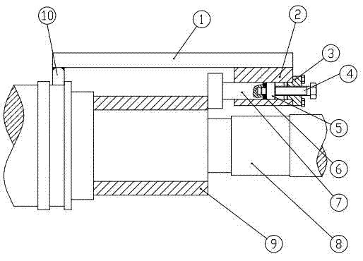
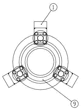
[0011] Such as figure 1 As shown, the middle section of the clamp of the present invention is a rectangular flat steel 1, one end welds the flat steel 10, and the other end welds a steel block 2 with a round hole; In the round hole of the block 2, the concentricity of the pin 5 and the indenter 7 is ensured by inserting the protrusion at the head of the pin 5 into the hole at the tail of the indenter 7; Screw in the stop bolt 4 in the central threaded hole of the stop bolt 4, and the tail end face of the stop bolt 4 butts against the pin 5.

[0012] After the heat-fit workpiece 9 is heat-fitted on the outer periphery of the shaft part 8, place the flat steel 10 of the fixture on the protrusion of the shaft part 8, and tighten the limit bolt 4 at the other end of the fixture so that the pressure head 7 is placed on the disc spring 6 Under...


PUM


Abstract

The invention discloses a clamp for preventing a shrinkage fit from shifting. The middle part of the clamp is rectangular flat steel. One end of the clamp is fixed with the steel flat while the other head is welded with a steel block provided with a circular hole. A pressure head, a disc spring and a pin are arranged in the circular hole of the steel block of the clamp in series. A bump of the pin head is inserted into the hole in the rear of the pressure head. A lid is fixed on the end surface of the steel block through a closing bolt and a central screwed hole of the lid is screwed to a limiting bolt. The rear end of the limiting bolt leans against the rear end surface. Materials required by the invention are easy to prepare and the invention is convenient to process. When the clamp is installed on a shaft, no tolerance fit is required so that the clamp is easy to install and disassemble, and convenient to use without a specially-assigned person. Because the pressing force applied by the clamp is persistent, the situation that the workpiece is cooled and not able to reset due to the spacing interval of mallet hitting manually can be avoided; and potential danger due to the shaft which erects up can be avoided, too. The invention not only reduces the working hours and improves the pressing quality, but also guarantees the safety under the premise that the shrinkage fit work does not shift.

Description

technical field [0001] The invention relates to the field of mechanical manufacturing equipment, in particular to a clamp for preventing displacement of a thermal sleeve. Background technique [0002] After the workpiece on the shaft is shrunk onto the shaft, the workpiece is displaced from its original position due to cooling contraction. The conventional method is to use a mallet to knock, or make the shaft vertical, and use the gravity of the shaft itself or press a heavy object on the machine to fix the machine. Hitting with a mallet requires a special person to be responsible, and the time interval between several times of beating is not easy to grasp, which wastes a lot of man-hours; and during the interval, the workpiece cools down and cannot be reset, making the pressing effect unsatisfactory. The method of utilizing the gravity of the shaft itself or pressing a heavy object on the machine part needs to make the shaft vertical, which increases the hoisting time and ...

Claims


Application Information

Patent Timeline
Patent Type & Authority Applications(China)
IPC IPC(8): B25B11/02B23P11/02
Inventor 桑超
Owner SEC ELECTRIC MACHINERY
Why Eureka
Try Eureka