
A semiconductor chip mounting and positioning method and positioning tool

A mounting positioning, semiconductor technology, applied in the direction of semiconductor/solid-state device manufacturing, electrical components, circuits, etc., can solve the problem of reducing the yield of packaged products, no process method for chip mounting position shift, and can not meet the quality requirements of wire bonding alignment and other problems, to achieve the effect of high yield and good consistency

Active Publication Date: 2017-02-15
WUXI ZHONGWEI GAOKE ELECTRONICS +1
View PDF7 Cites 0 Cited by
  • Summary
  • Abstract
  • Description
  • Claims
  • Application Information

AI Technical Summary

Problems solved by technology

The chip is placed on the highly fluid colloid. During the curing process, the colloid is heated and diffused, which will drive the chip to deviate from the original specified installation position, resulting in failure to meet the quality requirements of wire bonding alignment and reducing the yield of packaged products.
[0004] At present, the integrated circuit chip placement technology is mature, but there is no process method to realize the positioning of the chip installation position shift caused by the strong fluidity adhesive.

Method used


Image

  • A semiconductor chip mounting and positioning method and positioning tool
  • A semiconductor chip mounting and positioning method and positioning tool
  • A semiconductor chip mounting and positioning method and positioning tool

Examples


Embodiment Construction

[0020] Below the present invention will be further described in conjunction with embodiment.

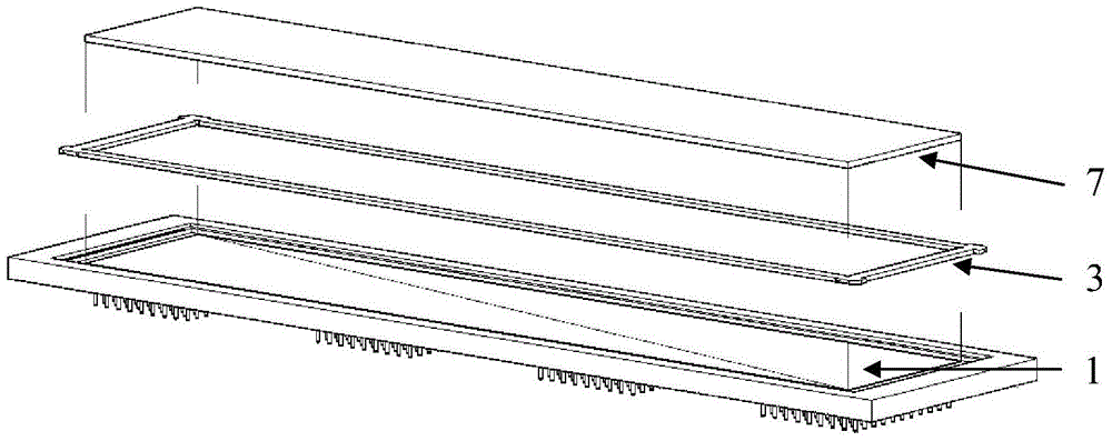
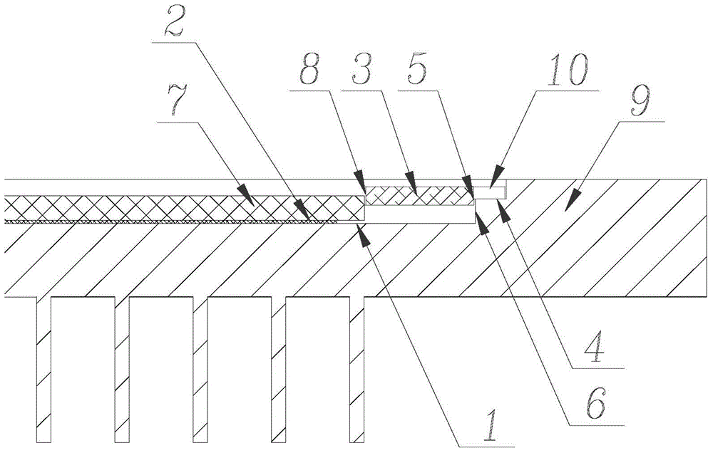
[0021] The invention utilizes a positioning tool to complete precise positioning and bonding of semiconductor chips. The outer frame of the positioning tool used should be adapted to the size of the core cavity of the shell, and the inner frame should be adapted to the size of the chip, so as to achieve the positioning function. In the embodiment of the present invention, the chip size is 168.3mm×31.29mm×0.76mm, the shell adopts CPGA packaging form, the shell core cavity bonding finger step size is 177mm x 38mm, and the shell core cavity size is 175mm x 36mm. Therefore, the design positioning fixture is a rectangular frame, and the four corners of the rectangular frame stretch out a foot rest 10 respectively. The thickness of the foot rest 10 is smaller than the thickness of the rectangular frame, and the lower edge of the foot rest 10 is higher than the lower edge of the rectangular...


PUM


Abstract

The invention relates to a method for mounting and positioning a semiconductor chip and a positioning jig. The method comprises the steps of firstly distributing an adhesive on the chip bonding region of a housing, putting the positioning jig on a bonding finger step in the cavity of the housing, putting the chip in the inner frame of the positioning jig so that the chip can be prevented from shifting out of a required position due to that the adhesive flows under heat when being cured, after the chip is placed, putting the semi-finished product device into a curing oven for curing the adhesive, after finishing curing, taking out the positioning jig from the cavity of the housing and obtaining the cured device. The method for mounting and positioning the semiconductor chip aims at preventing the chip from shifting due to the adhesive flowing in the curing process, and the positioning jig simple and reasonable in structure is adopted for realizing the chip positioning method, and the existing mounting device, the existing fixture, technical conditions and the like are not changed; after the chip is mounted and cured, the chip does not shift and satisfies the technical index of the location degree; the consistency of a batch of products is good and the rate of the finished products is high.

Description

technical field [0001] The invention relates to a method for fixing the position of a semiconductor chip during installation and a positioning fixture, belonging to the technical field of integrated circuit manufacturing. Background technique [0002] At present, the semiconductor chip bonding process is to distribute the patch glue on the chip bonding area of ​​the shell core cavity, and place the chip on the glue to ensure that the chip is assembled and positioned accurately after the glue is cured, and the glue on the back of the chip is evenly distributed to meet the requirements of automatic bonding. The need for alignment accuracy and flatness. [0003] The adhesive used for semiconductor chip attachment has different viscosity, stress, and fluidity, and the appropriate adhesive material should be selected according to product requirements. For products such as MEMS, optical sensor devices, and super-large-area chips, it is necessary to choose low-stress adhesives. Us...

Claims


Application Information

Patent Timeline
Patent Type & Authority Patents(China)
IPC IPC(8): H01L21/52H01L21/68
Inventor 葛秋玲张国华堵军李宗亚
Owner WUXI ZHONGWEI GAOKE ELECTRONICS
Learn More