A shot blasting device suitable for large steel processing

A shot blasting device and steel technology, which is applied to used abrasive processing devices, explosion generating devices, metal processing equipment, etc., can solve the problem of increasing the post-processing steps of the shot blasting device, prolonging the processing time, and reducing the working accuracy of the shot blasting device. and other problems to achieve the effect of ensuring shot blasting effect and improving work efficiency

Active Publication Date: 2022-07-05
临沂兴晟钢结构工程有限公司
View PDF0 Cites 0 Cited by
  • Summary
  • Abstract
  • Description
  • Claims
  • Application Information

AI Technical Summary

Problems solved by technology

[0003] Due to the different shapes of metal and steel castings, the structure of the shot blasting device currently on the market is relatively single, and the projectiles thrown by the shot blasting device are all set in a fixed direction. distance, but because the projection angle cannot be adjusted, the projected object cannot be effectively projected at 360 degrees, resulting in uneven surface of the processed object, which requires subsequent processing and prolongs the processing time. The shot blasting device has low working efficiency and a small scope of application, and has certain limitations in use, which not only leads to a reduction in the working accuracy of the shot blasting device, but also increases the post-processing steps of the shot blasting device, which brings great harm to people's use. To a certain extent, therefore, we propose a shot blasting device suitable for large-scale steel processing is of great practical value

Method used


Image

  • A shot blasting device suitable for large steel processing
  • A shot blasting device suitable for large steel processing
  • A shot blasting device suitable for large steel processing

Examples


Embodiment Construction

[0021] The technical solutions in the embodiments of the present invention will be clearly and completely described below with reference to the accompanying drawings in the embodiments of the present invention. Obviously, the described embodiments are only a part of the embodiments of the present invention, rather than all the embodiments. Based on the embodiments of the present invention, all other embodiments obtained by those of ordinary skill in the art without creative efforts shall fall within the protection scope of the present invention.

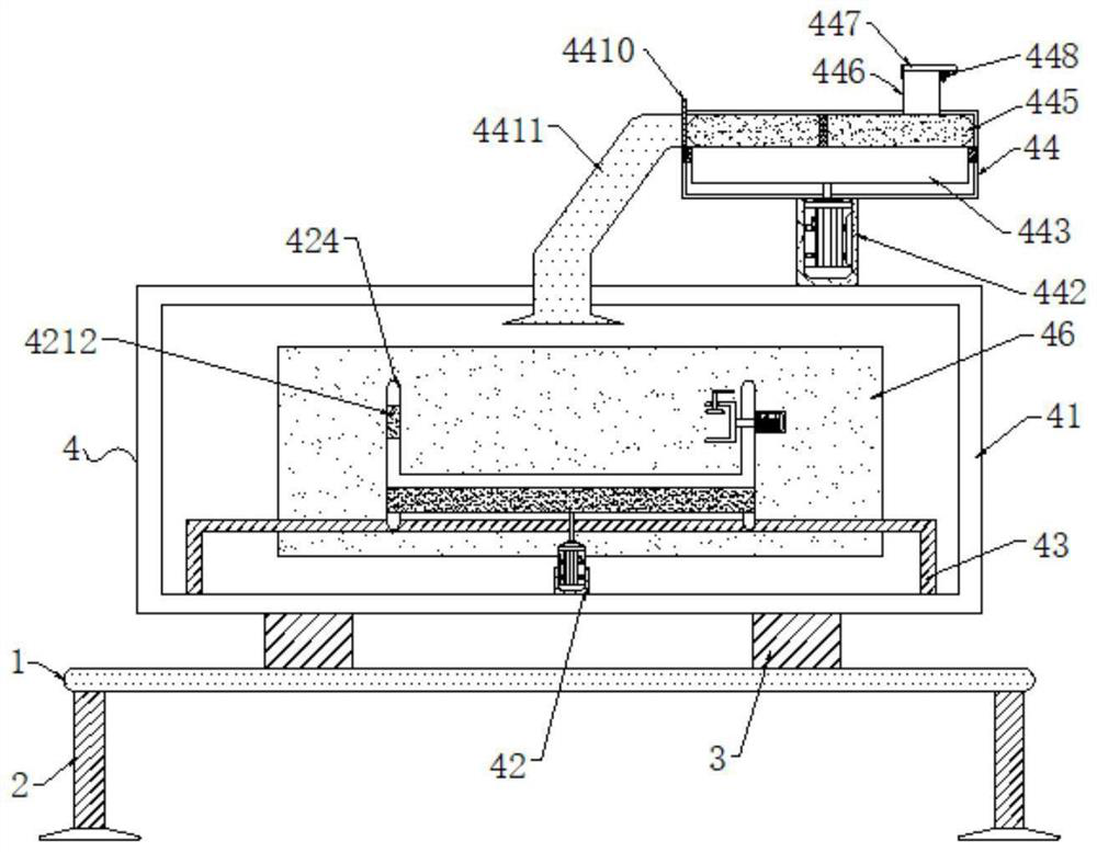
[0022] see figure 1 , The present invention provides a technical solution for a shot blasting device suitable for large-scale steel processing: a shot blasting device suitable for large-scale steel processing, comprising a base plate 1, the bottom of the base plate 1 is evenly provided with legs 2, and the top of the base plate 1 is provided with a blasting device Shot blasting device 4, the bottom of the shot blasting device 4 is co...


PUM


Abstract

The invention discloses a shot blasting device suitable for large-scale steel processing in the technical field of steel processing devices. The bottom is connected with a plurality of groups of bottom columns, and the bottom columns are fixedly connected to the top of the base plate. The shot blasting device includes an outer cylinder. The bottom of the inner cavity of the outer cylinder is provided with a lower bracket, and an inner adjustment is arranged on the lower bracket. The rear end surface of the outer cylinder is provided with an opening and closing door, and the opening and closing door and the outer cylinder are connected by hinge rotation, and the top of the outer cylinder is provided with a shot blasting component, and the shot blasting device for steel processing can be used for steel processing. Shot blasting at different angles and positions increases the use range of the device, greatly improves the working efficiency of the shot blasting device, and ensures the shot blasting effect of the device on steel.

Description

technical field [0001] The invention relates to the technical field of steel processing devices, in particular to a shot blasting device suitable for large-scale steel processing. Background technique [0002] Rebar shot blasting machine is a shot blasting equipment specially used for cleaning steel bars, wires, round bars and bars. It can apply strong shot blasting to the original steel surface, remove the rust layer, welding slag and oxide scale on it, so that it can obtain a uniform metallic luster, so as to improve the coating quality and anti-corrosion effect of the steel. [0003] Due to the different shapes of metal steel castings, the structure of shot blasting devices on the market is relatively simple at present, and the projectiles thrown by the shot blasting device are all set in a fixed direction. However, because the projection angle cannot be adjusted, it is impossible to effectively project the projectile object at 360 degrees. As a result, the surface of th...

Claims


Application Information

Patent Timeline
Patent Type & Authority Patents(China)
IPC IPC(8): B24C1/08B24C3/32B24C9/00B24C5/06
CPCB24C1/086B24C3/32B24C9/00B24C5/06B24C5/066Y02P10/20
Inventor 郝世博
Owner 临沂兴晟钢结构工程有限公司
Why Eureka
Try Eureka