Precise machining method of shaft end piece sealing ring B of stirrer
A processing method and mixer technology, applied in the field of shaft end parts processing, can solve the problems of poor accuracy and low processing efficiency, and achieve the effects of preventing movement, improving production efficiency, and uniform and stable relative position.
- Summary
- Abstract
- Description
- Claims
- Application Information
AI Technical Summary
Problems solved by technology
Method used
Image
Examples
Embodiment 1
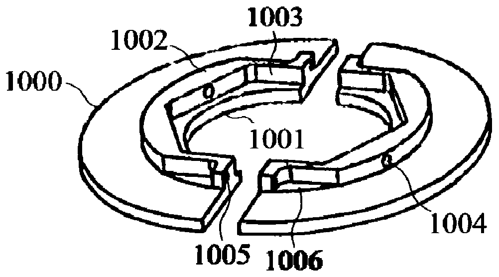
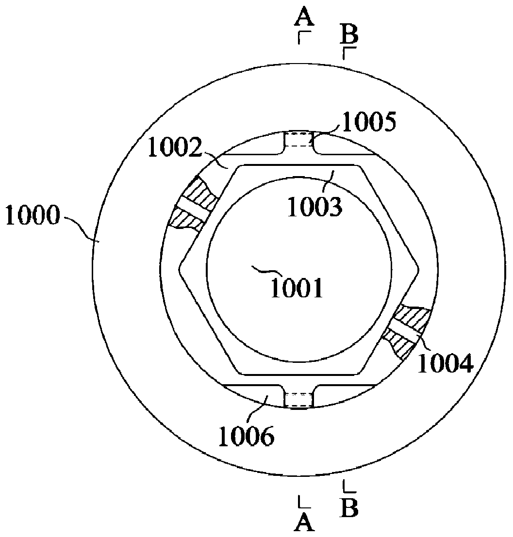
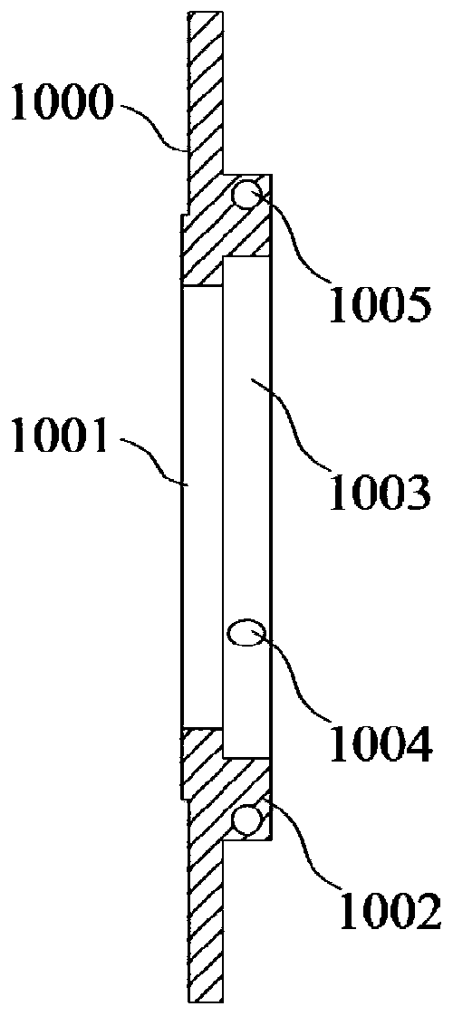
[0097] Such as figure 1 , figure 2 , image 3 with Figure 4 As shown, it is a schematic structural diagram of the seal B ring of the shaft end part. The processing equipment of this embodiment is designed based on the installation hole 1 1004 and the installation hole 2 1005 of the shaft end part seal B ring.
[0098] Such as Figure 13 with 15 As shown, the present embodiment makes improvements on the basis of the existing drilling machine. The main body of the drilling machine 100 and the workbench 200 are existing structures. In this embodiment, a T-shaped groove 210 is provided downwards on the upper surface of the workbench 200. A plurality of T-shaped grooves 210 are arranged side by side on the upper surface of the workbench 200 .
[0099] Such as Figure 5 , Image 6 with Figure 7 As shown, the present embodiment is also equipped with a processing tool 300. The mounting seat 1 of the processing tool 300 is an inverted T-shaped structure composed of a horizon...
Embodiment 2
[0106] This embodiment is modified on the basis of embodiment 1. The difference from embodiment 1 is that the fastening device of this embodiment is as Figure 12 As shown, it includes a threaded rod 8 and a knob 9. The threaded rod 8 is in the shape of a long rod, and the side wall is provided with a threaded structure. The knob 9 is in the shape of a disc. The diameter of the through hole 1001 also includes a long rod-shaped fastening rod 90 whose length is greater than the diameter of the circular through hole 1001 of the seal B ring of the shaft end piece. The solid rod 90 is placed between the knob 9 and the sealing B ring base 1000 of the shaft end piece to be processed, and the concave structure is set on the threaded rod 8, and the knob 9 is tightened, and the knob 9 acts on the fastening rod 90 and then the shaft end piece to be processed Seal the B ring for fastening.
Embodiment 3
[0108] A precise machining method for the seal B ring of the shaft end part of the mixer, the steps are as follows:
[0109] 1. Assembly:
[0110] a. Unscrew the knob 9, align the regular hexagonal counterbore 1003 of the seal B ring of the shaft end piece with the fixed block 1 for assembly, wherein, the installation hole 1005 of the seal B ring of the shaft end piece to be processed is located at the positioning block 1 5 or directly below the positioning block 2 6;
[0111] b. Unscrew the knob 9, and align the regular hexagonal counterbore 1003 of the seal B ring of the shaft end piece with the fixing block 2 3 for assembly, wherein, the installation hole 1005 of the seal B ring of the shaft end piece to be processed is located at the positioning block 3 directly below 7;
[0112] 2. Fastening:
[0113] Screw in the knob 9 on the threaded rod 8, and rotate the knob 9 to make the knob 9 contact with the base body 1000 of the seal B ring of the shaft end piece;
[0114] 3...
PUM
 Abstract
Description
Claims
Application Information
 - R&D
- Intellectual Property
- Life Sciences
- Materials
- Tech Scout
- Unparalleled Data Quality
- Higher Quality Content
- 60% Fewer Hallucinations
Browse by: Latest US Patents, China's latest patents, Technical Efficacy Thesaurus, Application Domain, Technology Topic, Popular Technical Reports.
© 2025 PatSnap. All rights reserved.Legal|Privacy policy|Modern Slavery Act Transparency Statement|Sitemap|About US| Contact US: help@patsnap.com


