Propeller blades with anti-icing coating

A technology for propellers and blades, applied in the direction of propellers, deicing devices, layered products, etc., can solve the problem of heater elements preventing the operation of the entire element, improve reliability and maintainability, save initial purchase and ongoing maintenance costs , the effect of reducing the radius

Active Publication Date: 2015-10-21
GE AVIATION SYST LTD
View PDF5 Cites 0 Cited by
  • Summary
  • Abstract
  • Description
  • Claims
  • Application Information

AI Technical Summary

Problems solved by technology

Another drawback of prior art heating systems is that damage to the heater element may prevent the entire element from functioning

Method used


Image

  • Propeller blades with anti-icing coating
  • Propeller blades with anti-icing coating
  • Propeller blades with anti-icing coating

Examples


Embodiment Construction

[0016] figure 1 The layer arrangement of the coating 6 applied to the propeller blade 1 is shown. The first adhesive layer 2 is arranged directly adjacent to the blade surface 1 . The polymer layer 3 is arranged on the adhesive layer 2 and is thus firmly fixed to the blade surface. The polymer layer 3 may comprise one or more rubber materials, such as neoprene. In addition, the polymer layer 3 may have a thickness in the range of, for example, 0.5 mm to 1.0 mm. On the neoprene layer 3 an adhesive coating 4 is arranged to provide a suitable surface for bonding a layer 5 of anti-icing material to the coating. The bond coat 4 may have a thickness of about 1 micron. The layer 5 of anti-icing material may have a thickness of about 3mm. The polymer layer 3 may be coloured, whereby wear of the layer of anti-icing material 5 and the coating 4 exposes the polymer layer to provide an indication of wear of the layer of anti-icing material 5 .

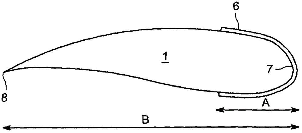
[0017] figure 2 The coating 6 appli...


PUM

PropertyMeasurementUnit
thicknessaaaaaaaaaa
thicknessaaaaaaaaaa
thicknessaaaaaaaaaa

Abstract

A propeller blade (1) for rotation about a hub assembly has disposed thereon at least along a leading edge (7) a coating (6) comprising an icephobic material, the coating (6) extending along the blade (1) from a radially inner region (9) to a radially outer region (10), wherein the radially outer region (10) is disposed between the blade root and the blade tip at a position where rotational forces on the blade (1) are sufficient, in use, to cause removal of ice from an uncoated blade (1).

Description

technical field [0001] The present invention relates to propeller blades for aircraft, in particular blades having means for preventing the accumulation of ice on the blades. Background technique [0002] Propellers fitted to aircraft approved to fly into known icing conditions must include means to prevent unacceptable levels of ice accumulation on the propeller blades. Ice accumulation on the airfoil section of a propeller blade affects the aerodynamic efficiency of the blade. There is therefore a need to limit the amount of ice allowed to accumulate on the blades in order to reduce aerodynamic efficiency losses. Furthermore, in order to prevent damage to the aircraft fuselage in icing conditions, it is necessary to minimize the size of the ice cubes that break off from the propellers. [0003] In the prior art, the electric heater system is controlled by a timer to provide cyclic heating of the blades to control ice shedding. The heater system includes: electrical heat...

Claims


Application Information

Patent Timeline
Patent Type & Authority Patents(China)
IPC IPC(8): B64C11/16B32B25/08B32B7/12B32B33/00
CPCB64C11/205B64D15/00
Inventor M·F·托肯
Owner GE AVIATION SYST LTD
Why Eureka
Try Eureka