Light guide plate, backlight module and display device

A technology for backlight modules and display devices, applied in lighting devices, fixed lighting devices, optics, etc., can solve problems such as difficulty in thinning liquid crystal display devices, scratches on optical films, and the need for rework

Inactive Publication Date: 2012-04-04
AU OPTRONICS CORP
View PDF2 Cites 8 Cited by
  • Summary
  • Abstract
  • Description
  • Claims
  • Application Information

AI Technical Summary

Problems solved by technology

[0003] However, due to the large number of components in the existing backlight module, it takes a lot of man-hours to assemble
In addition, since the light guide plate and the optical film in the backlight module are independent components, when there is an alignment error between the light guide plate and the optical film or the optical film is thermally deformed, the optical film may not be flat Attached to the surface of the light guide plate
Once this happens, the brightness and uni

Method used


Image

  • Light guide plate, backlight module and display device
  • Light guide plate, backlight module and display device
  • Light guide plate, backlight module and display device

Examples


Embodiment Construction

[0062] The present invention will be described in detail below in conjunction with the accompanying drawings and specific embodiments, but not as a limitation of the present invention.

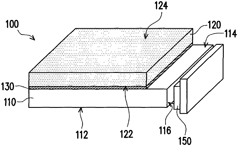
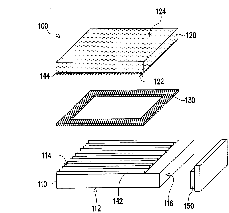
[0063] Figure 1A A light guide plate and a light emitting element according to an embodiment of the present invention are shown. Figure 1B for Figure 1A An exploded view of the structure shown. Figure 2A for Figure 1A A cross-sectional view of the structure shown. Figure 2B for Figure 2A A partial enlargement of area A of .

[0064] Please refer to Figure 1A , 1B, 2A and 2B, the light guide plate 100 includes a first transparent substrate 110 and a second transparent substrate 120 . The first transparent substrate 110 has an opposite first surface 112 , a second surface 114 , and a light incident surface 116 connecting the first surface 112 and the second surface 114 . The second transparent substrate 120 has a third surface 122 and a fourth surface 124 opposite to the third surfa...


PUM


Abstract

The invention relates to a light guide plate, which comprises a first light-penetrating substrate and a second light-penetrating substrate. The first light-penetrating substrate comprises a first surface, a second surface opposed to the first surface, and a light incidence face connecting the first surface and the second surface. Multiple first optical structures are equipped on the second surface. The second light-penetrating substrate comprises a third surface and a fourth surface opposed to the third surface. The second light-penetrating substrate is attached on the second surface of the first light-penetrating substrate. The third surface faces towards the second surface. Multiple second optical structures are equipped on the third surface. A light ray enters the first light-penetrating substrate through the light incidence face and then enters the second light-penetrating substrate through the first optical structures on the second surface and the second optical structures on the third surface and is finally emitted out of the second light-penetrating substrate through the fourth surface. The invention also provides a backlight module and a display device using the light guide plate. The light guide plate in the invention can provide excellent lighting effects.

Description

technical field [0001] The present invention relates to a light guide plate, a backlight module and a display device, and in particular to a light guide plate formed by joining two light-transmitting substrates each having an optical structure, and a backlight module using the light guide plate and display device. Background technique [0002] With the advancement of modern video technology, liquid crystal display devices have been widely used in mobile phones (mobile phones), notebook computers (notebook personal computers), personal computers (personal computer, PC) and personal digital assistants (personal digital assistant, PDA) ) on the display screens of consumer electronics products. However, since the liquid crystal display panel (LCD panel) of the liquid crystal display device does not have the function of emitting light, it is necessary to configure a backlight module under the liquid crystal display panel to provide the required backlight for displaying on the li...

Claims


Application Information

Patent Timeline
IPC IPC(8): G02B6/00G02B5/04F21S8/00F21V8/00G02F1/13357
Inventor 赖清坤曾德龙
Owner AU OPTRONICS CORP
Why Eureka
Try Eureka