Automatic lens assembly machine

An automatic assembly machine and lens technology, applied in installation, optics, instruments, etc., can solve problems affecting production efficiency, causing equipment waiting time, and inaccurate center positions

Inactive Publication Date: 2012-04-04
SYNERGY AUTOMATION CORP
View PDF5 Cites 11 Cited by
  • Summary
  • Abstract
  • Description
  • Claims
  • Application Information

AI Technical Summary

Problems solved by technology

[0006] The suction nozzle 241 of the transfer device 24 first transfers the lens B to the CCD vision device 25 to correct the center position of the lens B, and then transfers to the assembly operation station 22, which not only increases the workstation in the automatic operation, It also causes the waiting time of the equipment in the operation, which in turn affects the production efficiency
[0007] The two-dimensional CCD vision device 25 can only be used for displacement calibration of the X-Y two axes, and cannot be used for the calibration of the flatness of the third axis. Since the lens B is generally spherical, it is often inclined when placed. Therefore, When the lens B is placed obliquely, after controlling the suction nozzle 241 of the transfer device 24 to compensate for the X-Y two-axis displacement, the obtained center position of the X-Y two axes is not accurate, and the lens B may be tilted. are assembled in the lens barrel A, which affects the assembly quality

Method used


Image

  • Automatic lens assembly machine
  • Automatic lens assembly machine
  • Automatic lens assembly machine

Examples


Embodiment Construction

[0042] In order to make your examiner further understand the present invention, hereby give a preferred embodiment, and cooperate with the drawings to describe in detail as follows:

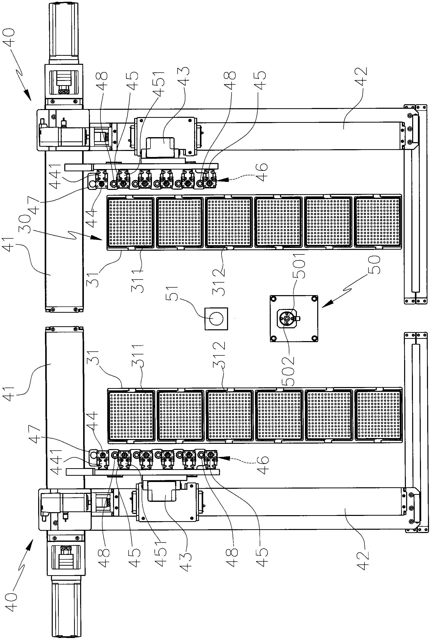
[0043] see image 3 , Figure 4 , Figure 5 , the automatic lens assembly machine of the present invention includes a feeding and receiving device 30, two transfer devices 40 and an assembly stand 50; the feeding and receiving device 30 is used to hold several lens elements; in this embodiment, the feeding and receiving device The device 30 is respectively provided with bearing seats 31 on the two sides of the assembling base 50, and according to the assembly type, several lens components are respectively supported, such as a tray (Tray) 311 for bearing the lens barrel, and a A plurality of trays (Tray) 312 for the lens are used for two transfer devices 40 to take materials; the two transfer devices 40 are relatively arranged on the side of the assembly base 50, and are respectively provided wi...


PUM


Abstract

An automatic lens assembly machine mainly comprises a material feeding and receiving device, at least two moving and loading devices and an assembly station seat, wherein the material feeding and receiving device is used for supporting and placing a plurality of kinds of lens components, the at least two moving and loading devices are respectively provided with a plurality of taking and placing devices for moving and loading the lens components and can drive the taking and placing devices to make displacement along three axial directions, moreover, counterpoint mechanisms are respectively and correspondingly arranged on the taking and placing devices, so that the central positions of the lens components can be respectively corrected, and the moving and loading devices are used for sequentially grabbing, moving and loading the lens components on the material feeding and receiving device; in the process of moving and loading, the central positions of the lens components can be corrected by the counterpoint mechanisms, and then the lens components are sequentially moved and loaded on the assembly station seat for carrying out the assembly operation of the lens; the timing collocated moving, loading and assembling are carried out by using the moving and loading devices, during the moving and loading, the central positions of the lens components can be corrected at the same time, therefore, the automatic lens assembly machine is suitable for different assembly types, and can carry out the assembly operation quickly and accurately so as to achieve the practical benefit of greatly improving the production efficiency.

Description

technical field [0001] The invention relates to an assembling machine, in particular to an assembling machine capable of automatically assembling lenses. Background technique [0002] Nowadays, technological products are changing with each passing day, bringing a lot of convenience to people, such as mobile phones with camera functions, PDAs, digital cameras, etc. Taking the camera lenses used in mobile phones as an example, the traditional manual assembly method consumes slowly time, resulting in reduced production efficiency, and the quality of lens assembly cannot be ensured; in order to improve the aforementioned problems, some operators have developed automated assembly machines; please refer to figure 1 , is the patent application No. 93108953 "automatic lens assembly machine" in Taiwan, China. The automatic lens assembly machine 10 includes a lens barrel workstation 11, several lens workstations 12 and a finished product workstation 13. The lens barrel workstation 11 ...

Claims


Application Information

Patent Timeline
Patent Type & Authority Applications(China)
IPC IPC(8): G02B7/02
Inventor 樊孝义
Owner SYNERGY AUTOMATION CORP
Why Eureka
Try Eureka