
Backplane of liquid crystal module and splicing structure thereof

A liquid crystal module and backplane technology, applied in the direction of thin plate connection, connection components, optics, etc., can solve problems such as high cost, poor structural strength, and reduced product performance

Active Publication Date: 2012-04-04
SHENZHEN CHINA STAR OPTOELECTRONICS TECH CO LTD
View PDF5 Cites 27 Cited by
  • Summary
  • Abstract
  • Description
  • Claims
  • Application Information

AI Technical Summary

Problems solved by technology

If the backplane is all made of aluminum, the cost is too high and the structural strength is poor; if all galvanized steel is used, the heat dissipation will not be good and the product performance will be reduced

Method used


Image

  • Backplane of liquid crystal module and splicing structure thereof
  • Backplane of liquid crystal module and splicing structure thereof
  • Backplane of liquid crystal module and splicing structure thereof

Examples


Embodiment Construction

[0028] In order to make the above-mentioned objects, features and advantages of the present invention more obvious and easy to understand, the preferred embodiments of the present invention are exemplified below, and are described in detail as follows in conjunction with the accompanying drawings:

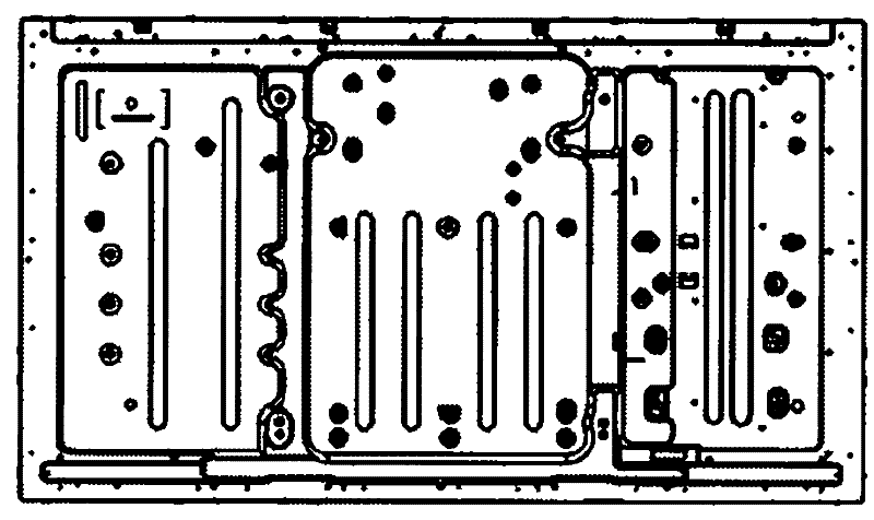
[0029] The liquid crystal module backplane of the present invention is designed by disassembling and segmenting the existing large-sized liquid crystal module backplane, and then splicing to form the backplane.

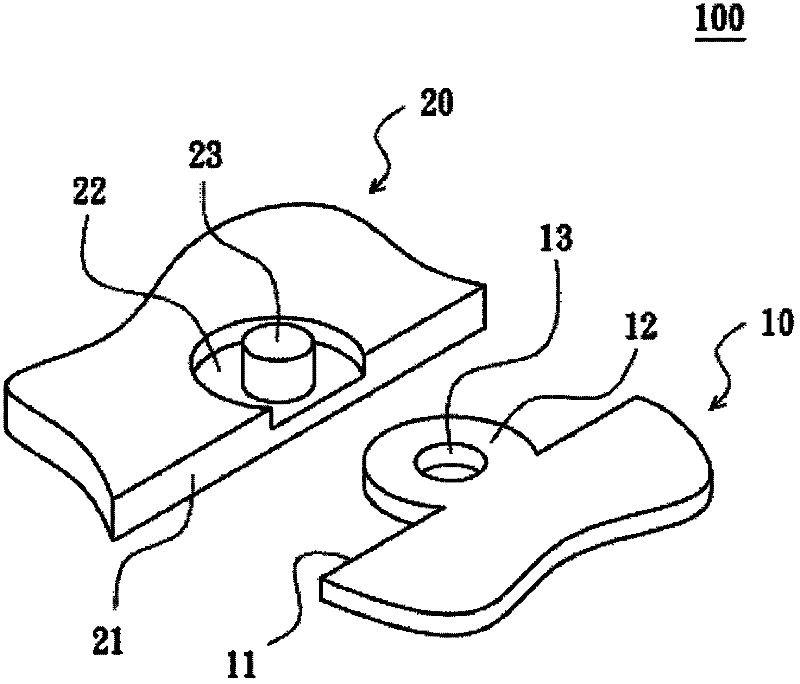
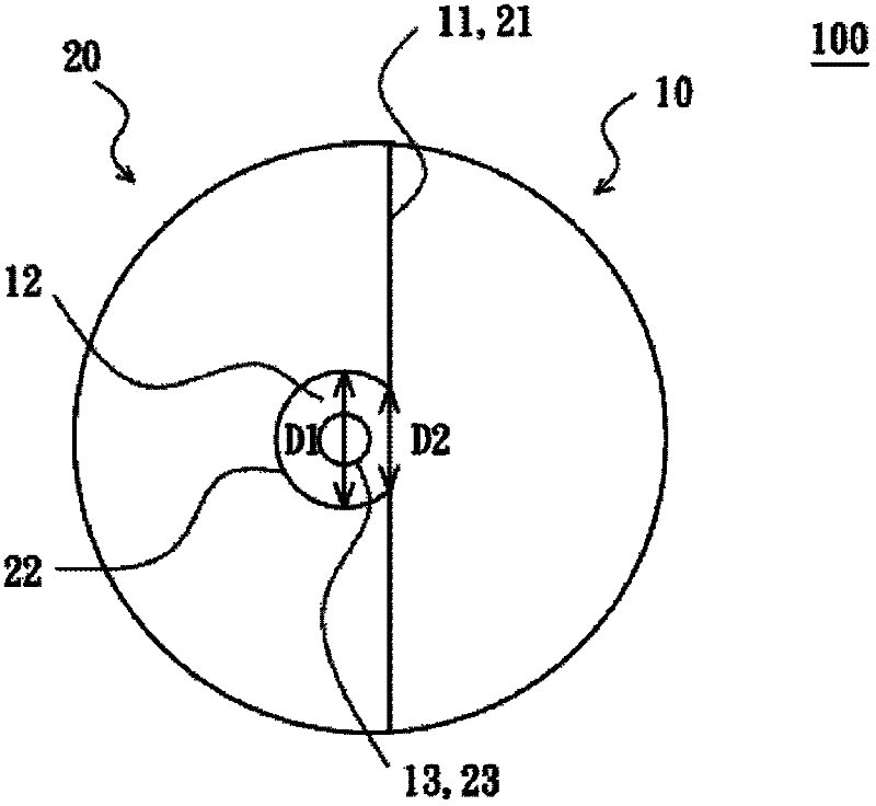
[0030] Please refer to Figure 2A and 2B shown, Figure 2A disclose a partial perspective view of a splicing structure of a liquid crystal module backplane according to the first embodiment of the present invention; and Figure 2B A partial front view of a splicing structure of a liquid crystal module backplane according to the first embodiment of the present invention is disclosed. The backplane of the liquid crystal module of the present invention is formed by at leas...


PUM


Abstract

The invention discloses a backplane of liquid crystal module and splicing structure thereof, wherein the liquid crystal module backplane is spliced by at least a first backplane and a second backplane, at least one splicing structure is arranged between the first backplane and the second backplane, the shapes of the two sides of the splicing structures are corresponded and embedded with each other, a fixing hole is set on the protruding part, a fixed column is correspondingly set inside the concave step part, the fixed column pierces the fixed hole for some distance, the end of the fixed column are forced to deform and expand the diameter of the column so as to fix the first backplane and the second backplane. The invention that different materials are made and formed into the backplane of liquid crystal module by the splicing structures is characterized by reducing material cost, and strengthening the splice strength.

Description

【Technical field】 [0001] The invention relates to a liquid crystal module backplane, in particular to a splicing structure of the liquid crystal module backplane. 【Background technique】 [0002] A liquid crystal display (LCD) is a flat panel display (FPD) that uses the characteristics of liquid crystal materials to display images. Compared with other display devices, it is lighter and thinner, with lower driving voltage and lower Power consumption and other advantages have become mainstream products in the entire consumer market. However, the liquid crystal material of the liquid crystal display cannot emit light by itself, and an external light source must be provided. Therefore, a backlight module is additionally provided in the liquid crystal display to provide the required light source. [0003] The assembly of the existing liquid crystal module is mainly to carry a light guide plate in a back plate, the light guide plate is provided with an optical film group, and anot...

Claims


Application Information

Patent Timeline
IPC IPC(8): G02F1/13
CPCG02F1/133308G02F1/1333G02F2001/133314F16B5/04G02F1/133314
Inventor 郭仪正萧宇均黄冲程加河阙成文李全杨流洋
Owner SHENZHEN CHINA STAR OPTOELECTRONICS TECH CO LTD
Learn More