Eureka AIR delivers breakthrough ideas for toughest innovation challenges, trusted by R&D personnel around the world.

Method For Making Liquid Crystal Display Panel

一种液晶显示面板、液晶的技术,应用在静态指示器、非线性光学、仪器等方向,能够解决不如预期等问题,达到下降时间缩短的效果

Active Publication Date: 2012-04-04
OPTOELECTRONIC SCI LLC
View PDF4 Cites 4 Cited by
  • Summary
  • Abstract
  • Description
  • Claims
  • Application Information

AI Technical Summary

Problems solved by technology

It can be seen that the falling time of the blue phase liquid crystal will increase with the increase of the driving voltage, which is not as expected

Method used


Image

  • Method For Making Liquid Crystal Display Panel
  • Method For Making Liquid Crystal Display Panel
  • Method For Making Liquid Crystal Display Panel

Examples


Embodiment Construction

[0034] The present invention will be described in detail below in conjunction with the accompanying drawings and specific embodiments, but not as a limitation of the present invention.

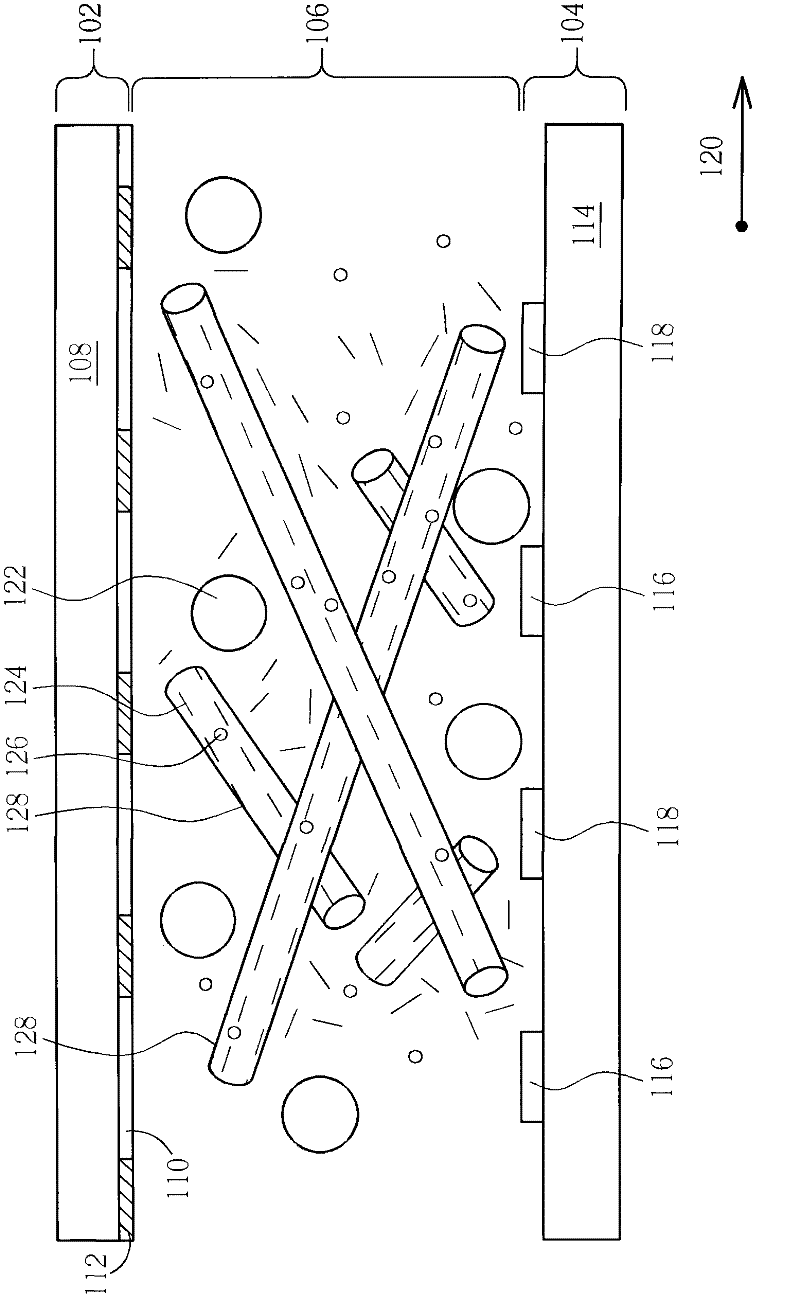
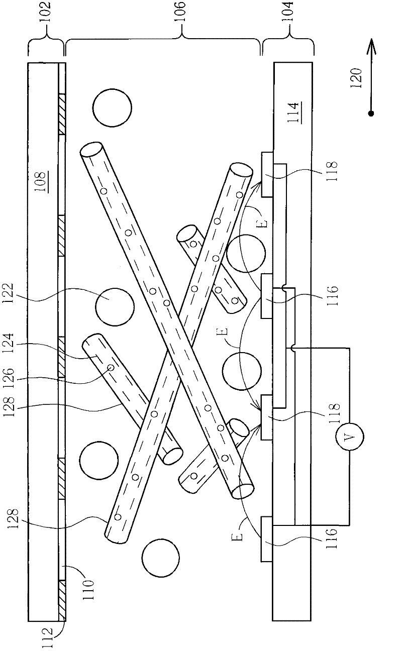
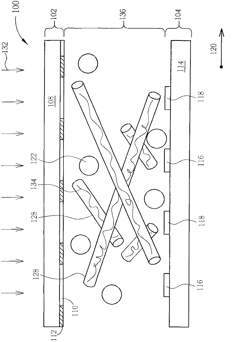
[0035] Please refer to Figure 1 to Figure 3 , Figure 1 to Figure 3 A method for manufacturing a liquid crystal display panel according to a first preferred embodiment of the present invention is shown. Such as figure 1 As shown, firstly, an upper substrate 102 , a lower substrate 104 and a liquid crystal mixture 106 are provided, and the liquid crystal mixture 106 is filled between the upper substrate 102 and the lower substrate 104 . In this embodiment, the upper substrate 102 is a color filter substrate, and the lower substrate 104 is a thin film transistor array substrate. Moreover, the upper substrate 102 may include a first substrate 108 , a color filter layer 110 and a black matrix 112 , and the color filter layer 110 and the black matrix 112 are disposed between the first substrate ...


PUM


Abstract

Provided is a method for making a liquid crystal display panel. The method comprises the following steps: providing an upper substrate, a lower substrate, and a liquid crystal mixture, with the liquid crystal mixture being filled between the upper substrate and the lower substrate; exerting an electric field upon the liquid crystal mixture; then stopping the exertion of the electric field; and irradiating energy light upon the liquid crystal mixture to form a liquid crystal layer. The method can reduce the drop time of a liquid crystal display panel.

Description

technical field [0001] The invention relates to a method for manufacturing a liquid crystal display panel, in particular to a method for manufacturing a liquid crystal display panel with a blue phase liquid crystal. Background technique [0002] Liquid crystal display panels have the characteristics of light and thin appearance, low power consumption, and no radiation pollution. They have been widely used in portable information products such as notebook computers (notebooks) and personal digital assistants (PDAs), and have gradually replaced traditional CRT monitor for desktop computer. Existing liquid crystal display panels use liquid crystal molecules to have optical anisotropy, use electric field to drive liquid crystal molecules to rotate to different alignment states, and match polarizers to present bright state and dark state. Generally, its response time (response time) ) takes more than 10 milliseconds. [0003] In order to solve the problem that the response time...

Claims


Application Information

Patent Timeline
Patent Type & Authority Applications(China)
IPC IPC(8): G02F1/1333G02F1/133G02F1/1343
CPCG02F1/1333G02F1/1343G02F1/133G02F1/137G02F2001/13793G02F1/13793
Inventor 曾德仁蔡正晔俞方正黄泰翔
Owner OPTOELECTRONIC SCI LLC
Why Eureka
Eureka Blog
Learn More