Gate drive circuit and display panel

A gate drive circuit and stage gate technology, applied in the direction of static indicators, instruments, etc., can solve the problem of deteriorating the instability of the display panel, and achieve the effects of shortening the falling time, improving the working stability, and improving the effect of stress

Active Publication Date: 2022-05-17
WUHAN CHINA STAR OPTOELECTRONICS TECH CO LTD
View PDF0 Cites 0 Cited by
  • Summary
  • Abstract
  • Description
  • Claims
  • Application Information

AI Technical Summary

Problems solved by technology

[0003] However, the gate drive circuit is easily affected by various reasons, so that it takes a long time for the falling edge of the output scan signal to drop to the preset low potential, which easily worsens the working instability of the display panel.

Method used


Image

  • Gate drive circuit and display panel
  • Gate drive circuit and display panel
  • Gate drive circuit and display panel

Examples


Embodiment Construction

[0027] The technical solutions in the embodiments of the present application will be clearly and completely described below in conjunction with the drawings in the embodiments of the present application. Apparently, the described embodiments are only some of the embodiments of this application, not all of them. Based on the embodiments in this application, all other embodiments obtained by those skilled in the art without making creative efforts belong to the scope of protection of this application.

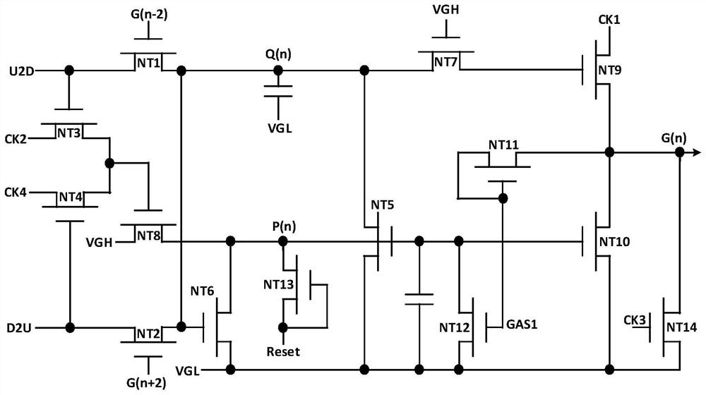
[0028] see figure 1 to the figure, such as figure 1 As shown, this embodiment provides a gate drive circuit, which includes transistor NT1, transistor NT2, transistor NT3, transistor NT4, transistor NT5, transistor NT6, transistor NT7, transistor NT8, transistor NT9, transistor NT10, transistor NT11, Transistor NT12, transistor NT13, transistor NT14 and two capacitors.

[0029]Wherein, one of the source / drain of the transistor NT1 and the gate of the transistor NT3 are both us...


PUM


Abstract

The present application discloses a gate drive circuit and a display panel. The gate drive circuit includes a plurality of cascaded gate drive units. The gate drive unit of the Nth stage adopts the same clock through the pull-down control module, the maintenance module and the pull-down module. The combined signal can quickly pull down the falling edge of the N-level scanning signal to the potential of the constant-voltage low-potential signal, effectively shortening the falling time of the N-level scanning signal from high potential to low potential.

Description

technical field [0001] The present application relates to the field of display technology, in particular to a gate drive circuit and a display panel. Background technique [0002] As a display component of an electronic device, a display panel has been widely used in various electronic products, wherein a gate driving circuit is an important component of the display panel. The gate drive circuit can also be called GOA (Gate Driver On Array, array substrate row drive) circuit, which uses the array (Array) process of the thin film transistor display to manufacture the gate (Gate) row scanning drive signal circuit on the Array substrate to realize A technology for the gate progressive scan driving method. [0003] However, the gate driving circuit is easily affected by various reasons, so that it takes a long time for the falling edge of the output scan signal to drop to a preset low potential, which easily worsens the working instability of the display panel. [0004] It sho...

Claims


Application Information

Patent Timeline
Patent Type & Authority Patents(China)
IPC IPC(8): G09G3/20
CPCG09G3/20
Inventor 曹海明
Owner WUHAN CHINA STAR OPTOELECTRONICS TECH CO LTD
Why Eureka
Try Eureka