Electrochromic unit and display device using same

An electrochromic and electrochromic layer technology, applied in electrical components, optical components, optics, etc., can solve problems affecting display image quality, short service life, chromatic aberration, brightness, etc.

Inactive Publication Date: 2012-04-04
J TOUCH CORPORATION
View PDF3 Cites 7 Cited by
  • Summary
  • Abstract
  • Description
  • Claims
  • Application Information

AI Technical Summary

Problems solved by technology

[0007] U.S. Patent Gazette, Autostereoscopic 3D display device and fabrication method thereof No. 2006087499, etc., the above-mentioned patents all use electrochromic materials as parallax barrier devices for displaying stereoscopic images, but M368088 and M371902 have common defects in their structures , all lack the necessary electrolyte layer of the electrochromic device. Due to the lack of an electrolyte layer that can provide ions to the electrochromic layer, the electrochromic device will not be able to produce a reversible reaction of oxidation or reduction to complete the coloring or decolorization change. Therefore, these In fact, the patent should not be implemented or the fading speed is extremely slow; in addition, the transparent electrode layer and the electrochromic material layer of the parallax barrier device are all set in a fence pattern, and the layered coating, sputtering or etching in the manufacturing process, Even each laminated layer must be accurately aligned, the manufacturing process is quite complicated, and all laminated layers are set in a fence pattern, resulting in a hollow area between each fence and fence, which will affect the overall light penetration, refraction or reflection, even if it is Ordinary 2D display may also affect the image quality of the display, causing problems such as chromatic aberration or uneven brightness, and its structural strength is low and its service life is short; while I296723 is a structure embedded in a liquid crystal display and formed on a color filter, and The electrochromic layers in all the above-mentioned patents use conventional electrochromic materials and color-changing mechanisms, which require a large driving voltage, so it is easy to cause material defects and short service life.

Method used


Image

  • Electrochromic unit and display device using same
  • Electrochromic unit and display device using same
  • Electrochromic unit and display device using same

Examples


Embodiment Construction

[0040] In order to enable your examiner to clearly understand the content of the present invention, only the following descriptions are provided together with the drawings, please refer to them.

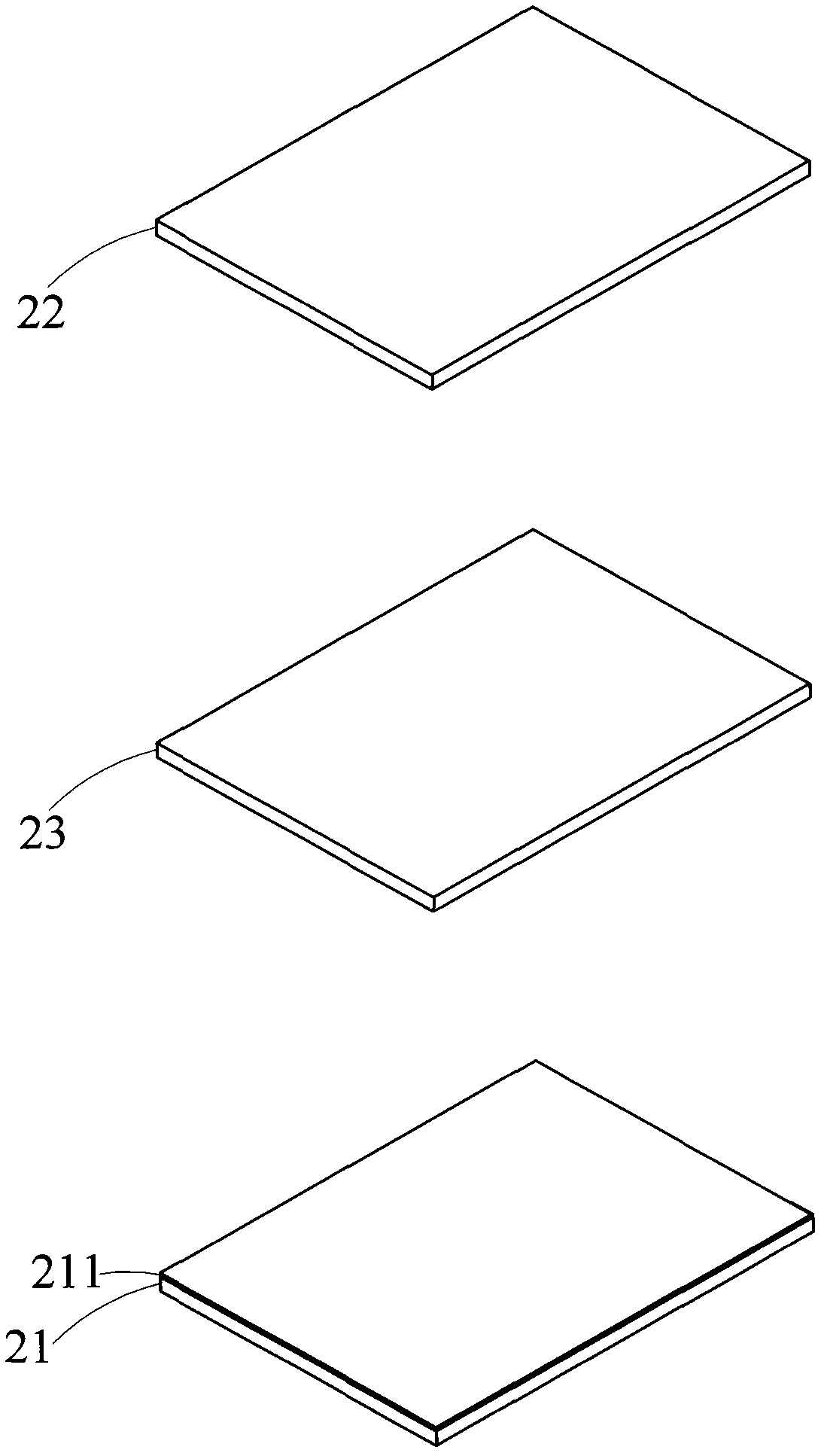
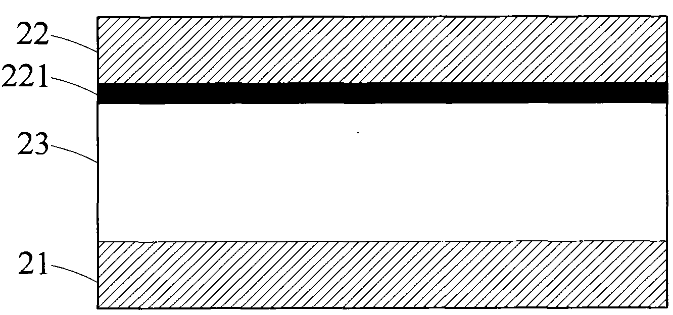
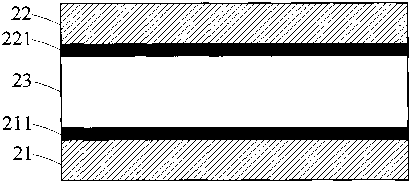
[0041] see figure 1 , figure 2 , image 3 As shown, it is a three-dimensional exploded schematic view of the first preferred embodiment of the present invention. As shown in the figure, the electrochromic unit 2 of the present invention includes a first transparent substrate 21, a second transparent substrate 22, and a An electrochromic layer 23 between a transparent substrate 21 and the second transparent substrate 22, and a first transparent conductive element 211, wherein the first transparent conductive element 211 can be arranged on the surface of the first transparent substrate 21 (such as figure 1 shown), or can be arranged on the surface of the second transparent substrate 22 (such as figure 2 shown), or the transparent conductive elements 211, 221 are simultaneously arr...


PUM


Abstract

The invention provides an electrochromic unit and a display device using the same. The electrochromic unit comprises a first transparent substrate and a second transparent substrate, wherein a transparent conducting element and an electrochromic layer are arranged between the first transparent substrate and the second transparent substrate. Therefore, the internal ion valence number of a material is changed by electrons, and when the ion valence number is subjected to the electrodes, the discoloration action caused by reduction and oxidation which is caused by electron dissipation, is provided. The electrochromic speed of the electrochromic unit is higher and more uniform than that of a traditional electrochromic material. The electrochromic unit has the advantages of high speed of coloration and discoloration and lower driving voltage. At the same time, the electrochromic unit is different from the coloration and discoloration change mechanism that an organic / inorganic electrochromic material depends on ion and electron dual injection or dual extraction.

Description

technical field [0001] The invention relates to a display device, in particular to an electrochromic unit and a display device using the unit. Background technique [0002] The principle of the well-known stereoscopic image display technology is to use binocular disparity to receive different images through the left and right eyes respectively, and finally fuse them into a stereoscopic image in the brain. In naked-eye stereoscopic display technology, it can be roughly divided into two types according to its structure: lenticular lens and barrier type. The main reason for the switching of images is that the lenticular lens (Lenticular) or the light barrier (Barrier) is combined behind the general display. After passing through the lenticular lens (Lenticular) or the light barrier (Barrier), all planar images will be distinguished as the left eye Image and right-eye image, unless it is a plug-in stereoscopic image display module, when it is not necessary to display a stereosc...

Claims


Application Information

Patent Timeline
Patent Type & Authority Applications(China)
IPC IPC(8): G02F1/153G02B27/22H04N13/00
Inventor 叶裕洲王昭懿叶宗和
Owner J TOUCH CORPORATION
Why Eureka
Try Eureka