Dynamic zoning method of side backlight zoning control system

A partition control and dynamic partition technology, applied to static indicators, instruments, etc., can solve the problems of changes in display partitions and backlight partitions, failure to achieve energy saving, etc.

Active Publication Date: 2012-04-04
TCL CORPORATION
View PDF5 Cites 14 Cited by
  • Summary
  • Abstract
  • Description
  • Claims
  • Application Information

AI Technical Summary

Problems solved by technology

[0005] But this fixed partition method has a disadvantage, refer to image 3 , in the two adjacent display subregions A and B in the liquid crystal screen 15, wherein the maximum brightness of the pixels of the display subregion A is 255 (white) and the maximum brightness of the pixels of the display subregion B is almost 0 (black). Area C at the junction with display area A has a small number of pixels with a maximum brightness of 255 distribution
In this case, if the fixed partition method is adopted, since the corresponding relationship and area between the backlight partition and the display partition are preset according to the LED light strips of the backlight module, the display partition and the backlight partition cannot be adjusted during the control process. Therefore, the maximum brightness of the backlight partition corresponding to the two display partitions needs to be adjusted to 100, and the corresponding LED strips need to be driven at the maximum luminous value, which cannot achieve the purpose of energy saving

Method used


Image

  • Dynamic zoning method of side backlight zoning control system
  • Dynamic zoning method of side backlight zoning control system
  • Dynamic zoning method of side backlight zoning control system

Examples


Embodiment Construction

[0032] In order to make the object, technical solution and advantages of the present invention clearer, the present invention will be further described in detail below in conjunction with the accompanying drawings and embodiments. It should be understood that the specific embodiments described here are only used to explain the present invention, not to limit the present invention.

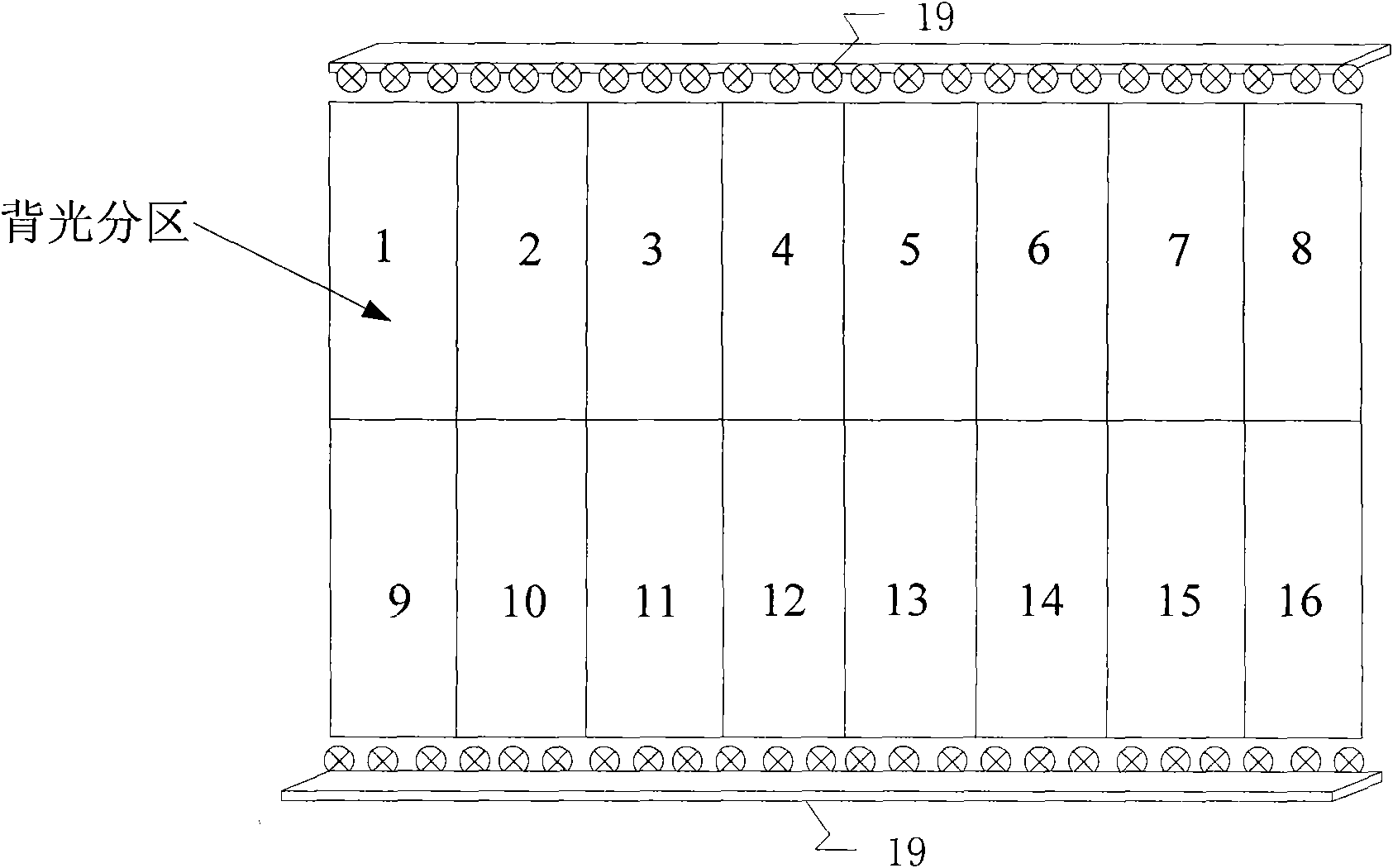
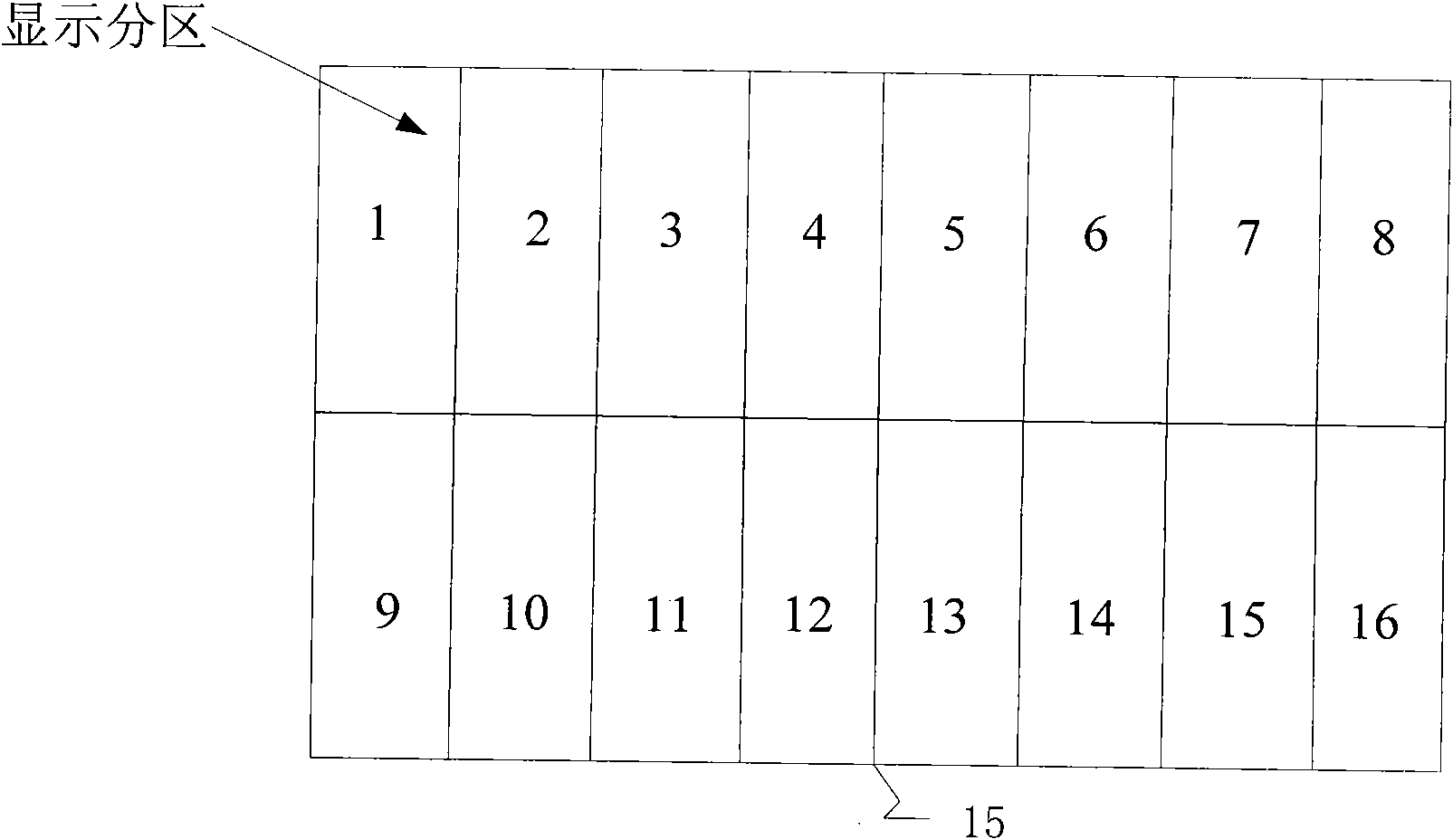
[0033] together with reference Figure 5 and Figure 6 , in the dynamic partition method of the side backlight partition control system provided by the present invention, at first the image analysis module determines several display partitions (first-level display partitions) according to the backlight partition, and then at the junction of every two adjacent display partitions Separately divide a temporary area. The width of this temporary area can be determined according to the light intensity of the LED light bar of the backlight partition corresponding to each display partition to the original...


PUM


Abstract

The invention provides a dynamic zoning method of a side backlight zoning control system, which comprises the following steps of: A, dividing out a plurality of primary display sub-zones according the backlight zoning condition; B, dividing out a plurality of temporary zones in the primary display sub-zones; C, according to image data in the primary sub-zones, dynamically merging the temporary zones into the primary display sub-zones to generate a plurality of secondary display sub-zones; and D, carrying out processing and dynamic backlight control on the image data according to the condition of the secondary display sub-zones. In the method, according to image contents in the primary display sub-zones, part of a region at the junction of each two adjacent primary display sub-zones is dynamically merged into a certain side so as to form the secondary display sub-zone of which the size is unequal to the sizes of the primary display sub-zones and ensure a zoning mode of a liquid crystal screen more reasonable, and thus, the energy consumption can be further saved and the quality of an image cannot be lost.

Description

technical field [0001] The invention relates to backlight control technology, in particular to a dynamic partition method of a side backlight partition control system. Background technique [0002] In the current LED side backlight partition control system of LCD TVs, the main control method is: according to the arrangement of LED light bars or the number of segments (the light bars can be segmented and controlled independently), the LCD screen is artificially divided into Several display partitions, each display partition corresponds to a backlight partition determined by the LED light bar in the backlight module, and then adjust the brightness of the LED light bar corresponding to the backlight partition according to the content of the image in each display partition, and then according to the corresponding The brightness of the LED light bar is used to compensate the brightness of the image in the display partition, and finally the compensated image data is output to the ...

Claims


Application Information

Patent Timeline
Patent Type & Authority Applications(China)
IPC IPC(8): G09G3/34G09G3/36
Inventor 施建华薛立勤
Owner TCL CORPORATION
Why Eureka
Try Eureka