Thermal management method and device for power battery pack with function of automatically controlling non-steady-state temperature field

A power battery pack and power battery technology, which is applied in secondary batteries, secondary battery repair/maintenance, circuits, etc., can solve the problems of increasing the weight of battery packs, large structural space, independent heating and cooling units, etc.

Inactive Publication Date: 2012-04-04
SHANGHAI ZHONGKE SHENJIANG ELECTRIC VEHICLE
View PDF3 Cites 29 Cited by
  • Summary
  • Abstract
  • Description
  • Claims
  • Application Information

AI Technical Summary

Problems solved by technology

[0005] At present, the thermal management methods of battery packs mainly adopt air cooling, liquid cooling and PTC heating; due to the above thermal management methods, the protection level of the battery pack is reduced, a large structural space is required, the weight of the battery pack is increased, and heating and cooling Unit independence and other issues, so it is necessary to develop a battery pack thermal management system with a new concept

Method used


Image

  • Thermal management method and device for power battery pack with function of automatically controlling non-steady-state temperature field
  • Thermal management method and device for power battery pack with function of automatically controlling non-steady-state temperature field
  • Thermal management method and device for power battery pack with function of automatically controlling non-steady-state temperature field

Examples


Embodiment Construction

[0029] In order to make the objects and advantages of the present invention clearer, the present invention will be further described in detail below in conjunction with the accompanying drawings and embodiments.

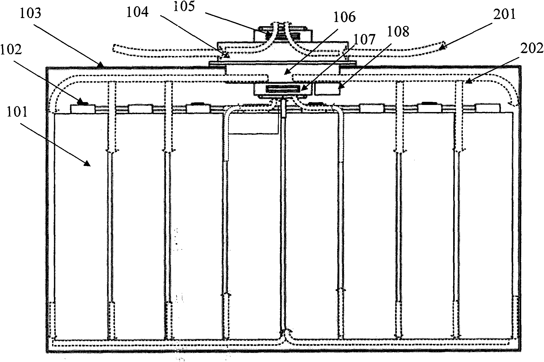
[0030] The power battery cell 101 is placed in the battery pack 103, and the temperature acquisition unit 102 is distributed on the pole of the power battery cell 101, and the hot end piece 104 of the semiconductor refrigeration heater and the external circulation fan 105 are placed outside the battery pack 103 , for heat transfer with the outside air. The cold end piece 106 of the semiconductor refrigeration heater and the internal circulation fan 107 are placed inside the battery pack 103 to perform air circulation and heat transfer in the battery pack 103 . The controller 108 of the thermal management system is integrated on the cold end piece 106 of the semiconductor refrigeration heater. The controller 108 controls the internal circulation fan 107, the external...


PUM


Abstract

The invention relates to a thermal management device for a power battery pack with a function of automatically controlling a non-steady-state temperature field, which comprises a battery pack, a temperature collection unit, a semiconductor cooler / heater, an external circulating fan, an internal circulating fan and a controller. A power battery monomer is arranged in the battery pack; the temperature collection unit is arranged on the pole of the power battery monomer; the semiconductor cooler / heater comprises a cold end plate and a hot end plate, automatic switching can be achieved between the two end plates, the two end plates are arranged on the shell of the battery pack, the cold end plate is arranged inside, the hot end plate is arranged outside, the cold end plate is a cooling plate and the hot end plate is a heat dissipating plate in forward powering-up, and the cold end plate is a heating plate and the hot end plate is a heat absorbing plate in reverse powering-up; the external circulating fan is arranged on the hot end plate of the semiconductor cooler / heater and is used for heat exchange between the hot end plate and external air; the internal circulating fan is arranged on the cold end plate of the semiconductor cooler / heater and is used for air circulation in the battery pack and heat exchange between the cold end plate and air in the batter pack; and the controller is used for controlling the thermal management device. Meanwhile, the invention discloses a method for implementing thermal management of the thermal management device.

Description

technical field [0001] The invention relates to a thermal management device and method for a power battery pack of an electric vehicle, in particular to a thermal management device and method for a power battery pack with an automatic control function of an unsteady temperature field. Background technique [0002] The power battery of an electric vehicle needs to be within a certain suitable temperature range (the temperature range is determined by the characteristics of the power battery itself). Each unit of the power battery will form an unsteady temperature field during the charging and discharging process. If the temperature of the power battery is If the temperature field is too high, too low, or if the temperature field is unevenly distributed, it will affect the charging and discharging performance of the battery and the overall life of the power battery pack, and even affect the reliability and safety of the battery in severe cases. [0003] The thermal management s...

Claims


Application Information

Patent Timeline
Patent Type & Authority Applications(China)
IPC IPC(8): H01M10/42H01M10/50H01M10/617H01M10/625H01M10/637H01M10/6572
CPCY02E60/12Y02E60/10
Inventor 张兆龙郑核桩
Owner SHANGHAI ZHONGKE SHENJIANG ELECTRIC VEHICLE
Why Eureka
Try Eureka