

System, device and method for load balancing
A technology of load balancing and load balancing equipment, applied in transmission systems, digital transmission systems, electrical components, etc., can solve the requirements for reducing the capability of load balancing equipment, reduce implementation complexity, implementation complexity and high hardware costs. The effect of reducing requirements, implementation complexity, and hardware cost
- Summary
- Abstract
- Description
- Claims
- Application Information
AI Technical Summary
Problems solved by technology
Method used
Image

Examples
Embodiment 1
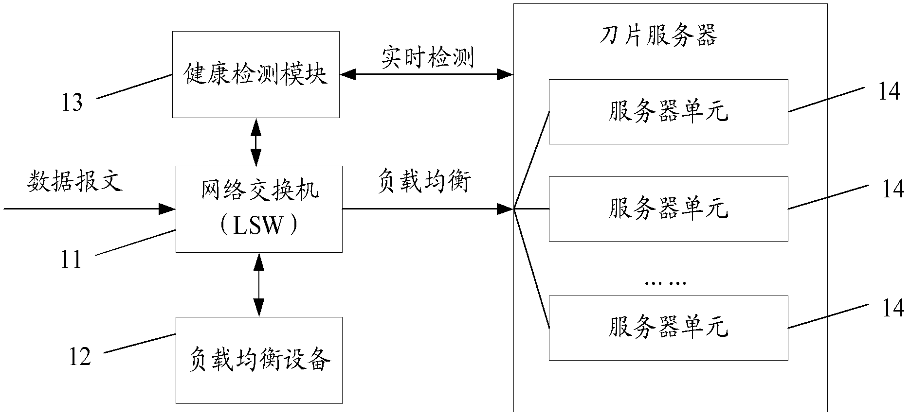
[0031] figure 1 A schematic structural diagram of a load balancing system provided by Embodiment 1 of the present invention is shown, and the system includes:
[0032] A network switch 11 , a load balancing device 12 , and a health detection module 13 , the network switch 11 is connected to the load balancing device 12 and multiple server units 14 in the blade server.
[0033] The network switch 11 is used to obtain feature information in the user data flow, and the feature information may include one or more of IP addresses and port numbers, or may also include other features that can characterize the user data flow and can be used by the network switch identified information.
[0034] Further, when the feature information conforms to the predetermined first load balancing strategy, forward the received data packets in the user data flow to multiple network switches connected to the network switch 11 according to the first load balancing strategy. The server unit 13 impleme...
Embodiment 2
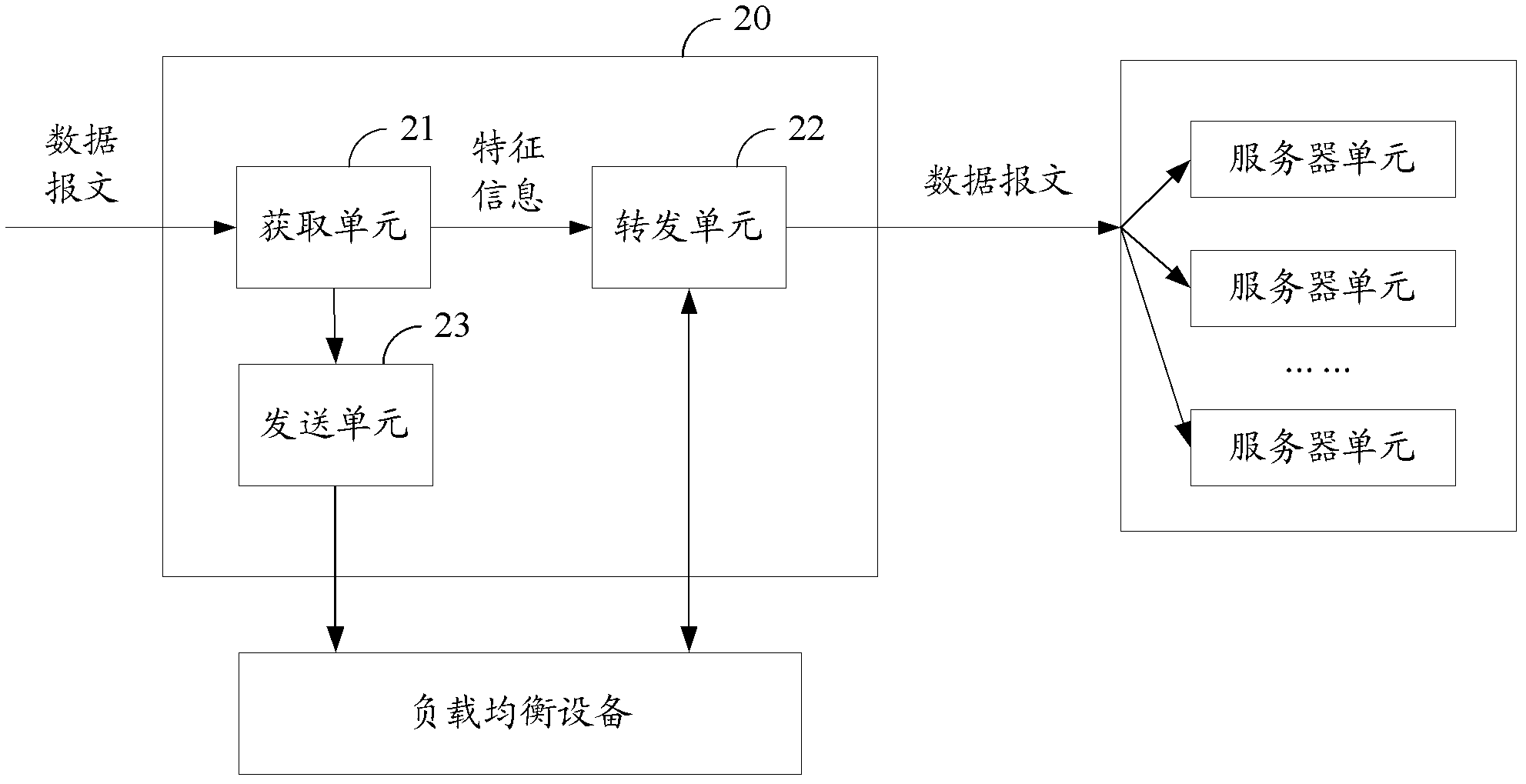
[0047] see figure 2 , based on the above-mentioned embodiments, the second embodiment provides a load balancing device, the entity of the load balancing device may be a network switch 20 , and the device includes: an acquiring unit 21 , a forwarding unit 22 , and a sending unit 23 .
[0048] The obtaining unit 21 is configured to obtain feature information in the user data stream, where the feature information includes one or more of IP address and port number.
[0049] The forwarding unit 22 is configured to forward the received data packets in the user data flow to the network switch connected to the network switch according to the first load balancing strategy when the characteristic information conforms to the predetermined first load balancing strategy. Multiple server units for low-level load balancing.
[0050] Wherein, the first load balancing policy defines a policy for forwarding data packets with specific characteristic information to a specific server unit.
[0...
Embodiment 3
[0065] see Figure 4 , based on the above embodiments, the third embodiment provides a load balancing method, the method includes:
[0066] 301. Acquire feature information in a user data stream, where the feature information includes one or more of an IP address and a port number.
[0067] 302. When the feature information conforms to a predetermined first load balancing strategy, forward the received data packets in the user data flow to multiple server units connected to the network switch according to the first load balancing strategy To achieve low-level load balancing, wherein the first load balancing strategy defines a strategy for forwarding data packets with specific characteristic information to a specific server unit.
[0068] Specifically, the external interfaces of multiple server units in the blade server are configured with unified IP addresses and ports. Compared with the second feature information of the first load balancing policy, when the second feature i...
PUM
 Abstract
Description
Claims
Application Information