Integrated decelerating clutch for washing machine motor

A technology of deceleration clutch and washing machine, which is applied to other washing machines, washing devices, textiles and papermaking, etc., can solve the problems of not much improvement of motor efficiency, complicated installation and connection, and many connecting parts of main parts, so as to improve the service life, Improved reliability and smooth operation

A technology of deceleration clutch and washing machine, which is applied to other washing machines, washing devices, textiles and papermaking, etc., can solve the problems of not much improvement of motor efficiency, complicated installation and connection, and many connecting parts of main parts, so as to improve the service life, Improved reliability and smooth operation

CN102409513AActive Publication Date: 2012-04-11宁波普尔机电制造有限公司

Image

  • Integrated decelerating clutch for washing machine motor
  • Integrated decelerating clutch for washing machine motor
  • Integrated decelerating clutch for washing machine motor

Examples


no. 1 example

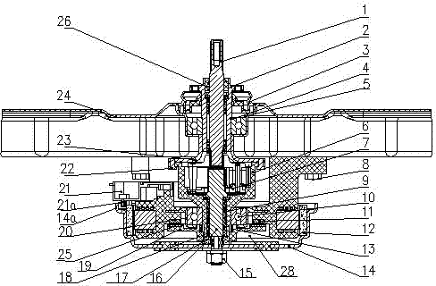
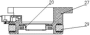
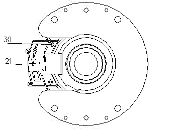
[0024] Such as Figure 1 to Figure 3 As shown, the integrated washing machine motor deceleration clutch of the present invention includes an input shaft 16, a stator 27, and an outer rotor 14 fixedly connected to the lower end of the input shaft 16, wherein the outer circumference of the outer rotor 14 extends upwards with the input shaft 16 to form a fixed stator. 27 inner cavity 28, the upper end of the stator 27 protrudes from the inner cavity 28 and is fixedly connected with the upper housing 24, and the Hall element feedback assembly 21 is installed on the shoulder made of the stator 27, and the Hall element feedback assembly 21 The lower edge is in clearance fit with the upper edge of the outer rotor 14 , and the Hall element feedback assembly 21 measures and controls the rotational speed of the outer rotor 14 . In the present invention, the motor stator 27 is directly installed on the lower part of the upper casing 24 through the stator fixing screws 8, and the body...

no. 2 example

[0033] Such as Figure 4 As shown, the brake wheel 6 of the present invention is transformed into a metal clutch shaft 32, and the connecting plate 23 is also transformed into a metal brake wheel 31, and the metal brake wheel 31 and the metal clutch shaft 32 are connected as one piece by riveting, and the metal brake The wheel 31 is interference fit with the dehydration shaft 2, the second oil bearing 33 and the third oil bearing 35 are arranged between the input shaft 16 and the brake wheel 6, and the second oil bearing 33 and the third oil bearing 35 are sealed and installed with Intermediate sealing ring 34. Other parts not described are the same as the first embodiment.

[0034] work process:

[0035] During washing machine washing: the electromagnetic coil 11 is not energized, and the clutch slider 19 slides downward under the spring force of the clutch spring 13, realizing the separation of the splines of the brake wheel 6 and the splines of the axle sleeve 17. The ou...


PUM


Abstract

The invention discloses an integrated decelerating clutch for a washing machine motor, which comprises an input shaft, a stator, and an outer rotor fixedly connected to the lower end of the input shaft, wherein the circumference of the outer rotor extends upward to form an inner chamber together with the input shaft for the placement of the stator, the upper end part of the stator extends out of the inner chamber and is fixedly connected with an upper casing, a Hall element feedback component is mounted on the stator provided with a convex shoulder, and the lower end of the Hall element feedback component is in clearance fit with the upper end of the outer rotor. Since the plastic encapsulation novel structure of the motor stator is adopted, and the motor stator in the structure is directly connected with the upper casing, the installation is simpler and more convenient, the cost of the complete machine is reduced, the axial stability is high, particularly, since the motor adopts the stator plastic encapsulating technology, the insulating property is good, and the safety performance is higher. The invention has the advantages of high efficiency, low noises, simple structure, and convenience in installation, can achieve a scrubbing function and is more suitable for mass production.

Description

technical field [0001] The invention relates to the technical field of a fully automatic pulsator washing machine, in particular to an integrated washing machine motor deceleration clutch. Background technique [0002] Existing technology is installed side by side with washing machine deceleration clutch and single-phase asynchronous motor as the washing machine newly released on the market, by belt pulley and belt transmission. The deceleration clutch of this type of washing machine has low efficiency, high noise, and poor practicability; therefore, relevant technical personnel have proposed a technical scheme in which the motor and the clutch are vertical and coaxially installed. For example, the patent No. ZL00260194.X Chinese invention patent discloses a fully automatic washing machine with cup-shaped rotor single-bearing motor and its special clutch device. efficiency. However, the patented technical solution is simply to install the single-phase asynchronous motor in...

Claims


Application Information

Patent Timeline
11 Apr 2012
Publication
CN102409513A
IPC
D06F37/30
Inventors
林其平; 左宜