
Floating bridge removing method

A technology of floating bridge demolition method and bridge method, which can be used in building maintenance, construction, building construction and other directions, and can solve problems such as long construction time and so on.

Inactive Publication Date: 2012-04-11
中天交通建设投资集团有限公司
View PDF6 Cites 2 Cited by
  • Summary
  • Abstract
  • Description
  • Claims
  • Application Information

AI Technical Summary

Problems solved by technology

Using this equipment for bridge demolition, the bridge can only be demolished in sections, and the construction time is long

Method used


Image

  • Floating bridge removing method
  • Floating bridge removing method
  • Floating bridge removing method

Examples


Embodiment Construction

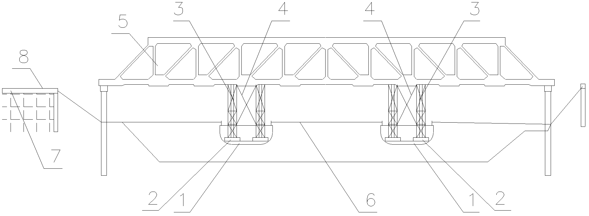
[0018] Combine Figure 1 to Figure 4 A detailed description of the embodiment of the floating bridge demolition method includes the following steps:

[0019] The first stage: the demolition of the old bridge deck in the construction stage, first remove the railings, then cut out the bridge deck, then remove the middle span concrete girder slab, and finally remove the side span girder slab; the specific process is to first seal the existing road, The bottom of the old bridge and the two bridges are equipped with safety protection nets. The old bridge components are manually removed by air compressors. The railings are removed first, and then the bridge deck paving; then the middle span concrete beam slabs are removed first, and then the side span beam slabs are removed. The connecting steel bars between the beam slab and the beam slab are cut by gas cutting, and the concrete in the screed is opened with a wind draft to reduce the binding and binding force between the beams and sla...


PUM


Abstract

The invention discloses a floating bridge removing method, which comprises the following steps of: 1, removing an old bridge surface; 2, preparing removal construction of a concrete truss of an old bridge; and 3, removing the concrete truss of the old bridge, namely making the bridge overhead through two barges for the first time, fixing a barge on the east side on a river bank on the east side so as to transversely move the old bridge to the upper part of a reinforced concrete foundation on the west side, filling water in a barge on the west side and sinking the barge. After the first movement is finished, the west end of the concrete truss is rolled through a steel roller on the concrete foundation and the east end of the concrete truss is supported by a barge bracket so as to move by hauling the barge until the barge is moved to the river bank, the barge sinks, the concrete truss is pulled to the river bank through a winch, and a crane assists in moving the bridge on the river bank. The method can be used for removing the old bridge, and because the concrete truss is removed by a barge and track combined monolithic translation method, the construction speed is high, navigation closure time is short, and influence of old bridge removal construction on normal operation of a navigation channel is reduced.

Description

Technical field [0001] The present invention relates to a bridge dismantling method. Background technique [0002] The traditional method of dismantling the bridge has a slow construction speed and a long sealing time, which has a greater impact on the normal operation of the channel. The Chinese utility model with patent number 200720070714.5 provides a bridge lifting equipment, including at least two Bailey truss load-bearing beams, each Bailey truss load-bearing beam includes multiple rows of Bailey trusses, and the Bailey truss includes multiple pieces The Bailey truss unit connected end to end, multiple rows of Bailey trusses are connected by supporting frames. The sleepers are placed on the upper side of each Bailey truss load-bearing beam. Multiple tracks are laid on the sleepers in parallel. The trolleys are respectively arranged on the track and can run on the track. The winch support beam is placed on the trolley and can move with the trolley, and the winch is set on t...

Claims


Application Information

Patent Timeline
IPC IPC(8): E01D24/00
Inventor 马科
Owner 中天交通建设投资集团有限公司
Learn More