Distribution valve, pumping mechanism and concrete pumping device

A technology of pumping mechanism and distribution valve, applied in mechanical equipment, components of pumping device for elastic fluid, pump components, etc., can solve the problems of poor sealing effect, low material suction efficiency, difficult compensation of sealing surface, etc. To achieve the effect of easy installation, high suction efficiency and simple structure

Active Publication Date: 2012-04-11
SANY AUTOMOBILE MFG CO LTD
View PDF5 Cites 4 Cited by
  • Summary
  • Abstract
  • Description
  • Claims
  • Application Information

AI Technical Summary

Problems solved by technology

[0006] In the distribution valve with the above structure, the seal between the side opening of the spool and the inner wall of the valve body is multiple sets of arc surface seals, the sealing effect is poor, and it is difficult to achieve high-pressure pumping; the side opening of the spool and the inner wall of the valve body It is very difficult to compensate after the sealing surface between the sides is worn, which leads to serious leakage of concrete between the suction chamber and the pumping chamber, which makes the distribution valve ineffective, which has a short service life
[0007] In addition, the distributing valve with this structure feeds the material into the valve body of the distributing valve through the valve core. The inside of the valve core is the feed chamber, and the outside of the valve core is the discharge chamber. The structure is more complicated, and the suction efficiency is low.

Method used


Image

  • Distribution valve, pumping mechanism and concrete pumping device
  • Distribution valve, pumping mechanism and concrete pumping device
  • Distribution valve, pumping mechanism and concrete pumping device

Examples


Embodiment Construction

[0043] In order to enable those skilled in the art to better understand the technical solutions of the present invention, the present invention will be further described in detail below with reference to the accompanying drawings and specific embodiments.

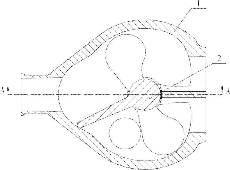
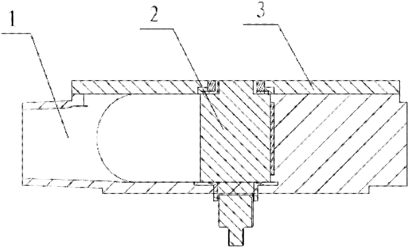
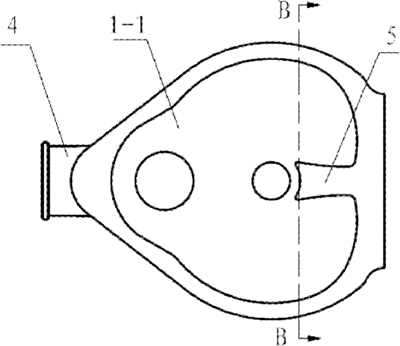
[0044] Please see Figure 1-Figure 8 , figure 1 It is a schematic structural diagram of a specific implementation of the distribution valve provided by the present invention; figure 2 for figure 1 A-A sectional structure diagram of the middle distribution valve; image 3 for figure 1 Schematic diagram of the middle valve body; Figure 4 for image 3 Schematic diagram of the sectional structure in the direction of B-B; Figure 5 for Figure 4 Schematic diagram of the method structure at middle I; Image 6 for figure 1 The structure diagram of the middle spool; Figure 7 for Image 6 Schematic diagram of the front view of the middle spool; Figure 8 for Image 6 Side sectional view of the structure of the middle valve core.

[004...


PUM


Abstract

The invention relates to the technical field of concrete pumping devices, and discloses a distribution valve. The distribution valve comprises a valve body and a valve core in the valve body, wherein the valve body is provided with a discharge port, a first suction port and a second suction port; a partition board for dividing the cavity of the valve body into a left cavity and a right cavity is arranged at the outer side of the valve core; when the valve core rotates relative to the valve body to a left limit position, the left side face at an end of the partition board abuts against the inner wall at the left side of the valve body, the discharge port is communicated with the first suction port, and the left cavity is communicated with a concrete hopper; and when the valve core rotates relative to the valve body to a right limit position, the right side face at an end of the partition board abuts against the inner wall at the right side of the valve body, the discharge port is communicated with the second suction port, and the right cavity is communicated with the concrete hopper. The distribution valve can effectively compensate for the clearance resulting from abrasion, and thus the service life of the distribution valve is prolonged. The invention also discloses a pumping mechanism with the distribution valve, and a concrete pumping device with the pumping mechanism.

Description

Technical field [0001] The invention relates to the technical field of concrete pumping equipment, in particular to a distribution valve. The present invention also relates to a pumping mechanism having the above-mentioned distribution valve and a concrete pumping device having the pumping mechanism. Background technique [0002] At present, the commonly used distribution valves for concrete pumping equipment include gate valves, S valves, C valves, skirt valves, etc. [0003] The S valve is installed in the hopper, and through the swing of an S-shaped elbow in the hopper, it connects two conveying cylinders in sequence to realize the concrete suction and pumping process. The S valve has a simple structure, good sealing effect, high-pressure pumping, and a wide range of applications. However, the S valve is placed inside the hopper, making the hopper a load-bearing part, and the structure is cumbersome; and because the S valve is placed inside the hopper, maintenance is difficult...

Claims


Application Information

Patent Timeline
Patent Type & Authority Applications(China)
IPC IPC(8): F04B53/10
Inventor 汤如龙李建涛李继波
Owner SANY AUTOMOBILE MFG CO LTD
Why Eureka
Try Eureka